The parking brake control valve is used to control the spring energy accumulators of the parking and spare brake drive (Fig. 1, a - c)
The manual brake valve is used to control the spring energy accumulators of the drive of the parking and spare brake systems
According to the principle of operation, the reverse-acting brake valve controls pneumatic elements that operate when compressed air is released
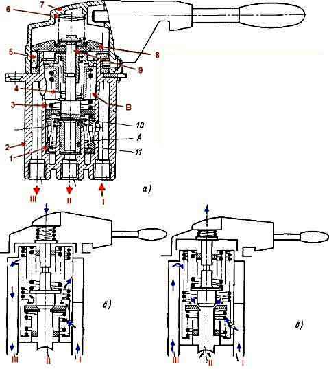
In the initial position (without braking, Figure b), the guide cap 8 and rod 9, under the action of their springs, occupy the lowest positions, and the exhaust valve 10, separated by the edge of the rod 9 from the piston seat 11, disconnects terminal “I” from the atmospheric terminal "II" and reports the output of "I" with the output of "III".
Compressed air through the hole in the piston 11 enters the cavity “A” and through the inlet window of the valve seat, made at the bottom of the piston 11, into the cavity “B”, from where it passes through the vertical channel to terminal “III” and then to the accelerator valve , which supplies compressed air to the cylinders of spring energy accumulators.
The springs of energy accumulators are compressed under the influence of compressed air.
To activate the spare brake system, you must turn the valve handle. In this case (Figure (c)), the guide cap 8 rotates together with the cover 7.
Sliding along the helical surfaces of the shaped protrusions of the ring 5, the cap 8 rises up and carries the rod 9 with it.
The lower edge of the rod 9 comes off the valve 10 and the latter, under the action of the spring 1, sits in the seat of the piston 11, disconnecting terminal “I” from terminal “III” and communicating the atmospheric terminal “II” with terminal “III”.
The supply of compressed air from terminal “I” to terminal “III” is stopped, and the compressed air from the control line of the accelerator valve through terminal “III”, valve hole 10 and terminal “II” is released into the atmosphere until the pressure in cavity "A" under piston 11 will not overcome the total force of the balancing spring 3 and the pressure on the piston in cavity "B".
If the forces are equal, the piston 11 together with the valve 10 rises until the valve seats on the edge of the rod 9.
The release of air from the control line of the accelerator pump through terminal “III” stops, i.e., a follow-up action is carried out.
When compressed air is released from the control line of the accelerator valve, the latter disconnects the cavity of the spring energy accumulator cylinders from the supply line and connects them to the atmospheric outlet of the accelerator valve.
Compressed air from the cylinders is released into the atmosphere, and spring energy accumulators brake the wheels of the rear bogie of the car.
The characteristics of the energy accumulator springs are selected in such a way that they provide a direct dependence of the pressure, and, consequently, the braking forces on the wheels on the angle of rotation of the handle.
The faucet stopper has an automatic return of the handle to its original position when it is released
To activate the parking brake system, you must turn the valve handle all the way back, where it is secured with a locking latch.
In this case, the air from port “III” completely escapes into the atmospheric port “II”, since the piston 11 rests against the spring limiter 4 and the valve 10 does not reach the lower edge of the rod 9.
To release the parking brake system, you must turn the crane handle forward all the way.
In this case, compressed air will flow from the air cylinder into cylinders with spring energy accumulators. Under the influence of compressed air, the springs are compressed and the brake mechanisms are released
Replacing the parking brake system control valve
We replace the faucet in case of the following malfunctions:
- - piston and valve freezing;
- - damage to the sealing rings;
- - mechanical damage to the body, handle, and its fixing mechanism, impairing the normal operation of the crane
Tools required: screwdriver, wrenches 10, 12, 14, 17
Removing the tap
We prepare the car and bleed air from the receivers of the 19th circuit of the parking brake system

Diagram of the pneumatic drive of the brake systems: 1 - brake chambers type 24; 2 - pressure gauge; 3 - auxiliary brake system control valve; 4 - pneumoelectric switch for the trailer solenoid valve; 5 - pneumatic cylinder for driving the engine stop lever; 6 - compressor; 7 - parking brake system control valve; 8 - water separator; 9 - pressure regulator; 10, 28 - single protective valves; 11 - triple protective valve; 12 - two-section brake valve; 13 - pneumatic cylinders for driving the flaps of the auxiliary brake system mechanism; 14 - circuit receiver; 1.15 - pressure drop warning lamp switches; 16 - circuit receivers; 11, 17 - condensate drain taps; 18 - consumer receiver; 19 receivers of circuit "III"; 20 - dual-line bypass valve for emergency brake release; 21 - two-line bypass valve; 22 - accelerator valve; 23 - switch for the parking brake system warning lamp; 25 - brake chambers; 24 - control valve for the brake systems of a trailer with a two-wheel drive; 26 - brake signal warning lamp switch; 27 - control valve for trailer brake systems with a single drive; 29 - disconnect valves; 30 - connecting heads of the "Palm" type; 31 - connecting head type “A”; A; IN; WITH; D - control valves; P - to the supply line of the two-wheel drive; R - to the connecting line of the single-drive drive; N - to the brake (control) line of the two-wheel drive
Unscrew the union nuts of the pipelines leading to the tap and disconnect the pipelines from the tap fittings
Unscrew the nuts of the screws securing the faucet to the bracket and remove the faucet
Installation of the faucet
Install the faucet onto the bracket and secure it
Connect the pipelines to the tap fittings and tighten the union nuts of the pipelines
Start the engine, create pressure in the pneumatic drive of the brake systems and check the operation of the crane in place and in motion
Repair of the parking brake system control valve
To complete the task you will need the following tools: a vice with soft jaws, a screwdriver, special pliers I801.23.000-01, a set of probes, pliers, a hammer
Disassembly of the crane
Install the brake valve in a vice with the lid up
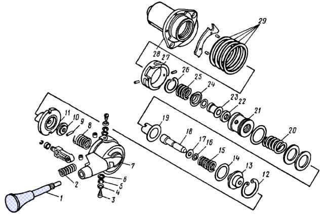
Parking brake system control valve: 1 - handle; 2, 8,15, 20, 25 - springs; 3 - screw; 4, 6,10,17, 29 - washers; 5 - spring washer; 7 - cover; 9 - pin; 11 - guide cap; 12, 26 - thrust rings; 13 - guide; 14,16, 27 - rings; 18 - rod; 19 - spring plate; 21 - piston; 22 - valve ring; 23 - valve body; 24 - support washer; 28 - body
Unscrew screws 3 with washers 4, 5, 6 securing valve cover 7 to body 28
Remove the cover assembly with handle 1 and spring 2 from the body
Unscrew handle 1 from cover 7
Remove pin 9 from rod 18, remove washer 10, cap 11
We remove from the body 28 the thrust ring 12, guide 13, ring 14, spring 15, rod 18, washer 17, ring 16, plate 19, spring 20, piston assembly 21
Remove the thrust ring 26 from the piston 21, remove the valve ring 22, body 23, support washer 24, spring 25
Remove the valve body 28 assembled with washers 29 and ring 27 from the vice
We wash the brake valve parts in diesel fuel and blow with compressed air
Assembling the tap
Install valve ring 22, valve body 23, support washer 24, spring 25, thrust ring 26 into piston 21
Note: Before installation, coat the working surface of the valve body with Tsiatim-221 lubricant
Install housing 28 assembled with washers 29 and ring 27 in a vice
Install the piston 21 assembly, rod 18, spring 20, plate 19, washer 17, ring 16, spring 15, guide 13 with ring 14 and thrust ring 12 into the valve body
Note: before installation, coat the working surface of the piston and rod with Tsiatim-221 lubricant
Install the guide cap 11 and washer 10 into the valve body
Install pin 9 into the rod
Screw handle 1 into valve cover 7
Install cover 7 assembled with handle and spring 2 on valve body 28
Screw the 3 screws securing the cover with washers into the faucet body
Remove the brake valve from the vice
Adjust the gap between the faucet cover and the washer in the following order:
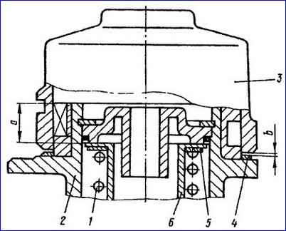
After installing spring 1 and plate 6, compress the spring to size a=13.7 -0.1 mm from the upper end of body 2 to the upper end of plate 6, while the spring force should be equal to 127 .5-152.0 N (13.0-15.5 kgf).
If this force is less than 127.5 N (13.0 kgf), then by replacing position 5 of the washer (part 100-3537095 or 1003537097), bring the spring force to the required value.
Installing one washer (part no. 100-3537095) increases the spring force by 41.7 N (4.25 kgf) and provides a pressure drop of 34.3 kPa (0.35 kgf/cm 2), and installing one washer is part. 100-353797 increases the spring force by 25.0 N (2.55 kgf) and provides a pressure drop of 20.6 kPa (0.21 kgf/cm 2).
Measure the gap b between cover 3 and washer 4, which should not exceed 0.15 mm.
If this gap is larger, then combine washers (part. 100-3537092) with a thickness of 0.15 mm, (part. 100-3537093) with a thickness of 0.2 mm and (part. 100-3537094) with a thickness of 0.3 mm and place it on washer 4 between cover 3 and body 2 so that the gap remains no more than the specified value.
Coat the washers with a thin layer of lubricant Tsiatim-221. Washer 4 (part no. 100-3537091), 0.5 mm thick, remains permanently at the bottom.
Check whether the crane lever returns easily when turning it 45 and 70º from position “I”
We test the brake valve for operability and tightness
Order tests:
Connect the tap according to the diagram shown in the figure
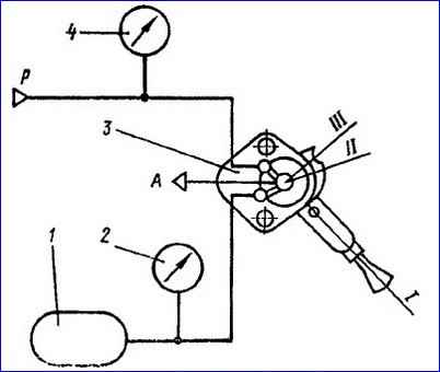
Set the pressure on pressure gauges 4 and 2 equal to 736 kPa (7.5 kgf/cm 2). In this case, air should not escape from terminal “A”
We slowly move the tap handle 3 from position “I” to position “III”. There should be no jamming when moving the handle, and it should easily lock into position "III".
When the handle is turned at an angle of up to 70º, it should automatically return to the “I” position.
Slowly turn the handle from position “I”. When turning the handle 8-10º, pressure gauge 2 should show a pressure drop of no more than 147 kPa (1.5 kgf/cm 2).
With further rotation of the handle, the pressure should gradually decrease to 0, and with the reverse movement it should gradually increase from 0 to 539.4 kPa (5.5 kgf/cm 2).
The stepwise change should not exceed 29.4 kPa (0.3 kgf/cm 2). The pressure drop on pressure gauge 2 to 0 should be achieved when the handle is turned 60-70º.
If there is residual pressure, eliminate it by installing the washer (part no. 1003537095) above the spring, as indicated in step 1 of transition 19.
Set the handle to position “III”. In this case, the pressure on pressure gauge 2 should be equal to 0, and no air should come out of terminal “A”
Return the handle to position “I”. The tap must be sealed in any position of the handle.
")

")
")
")
")
")
")
")