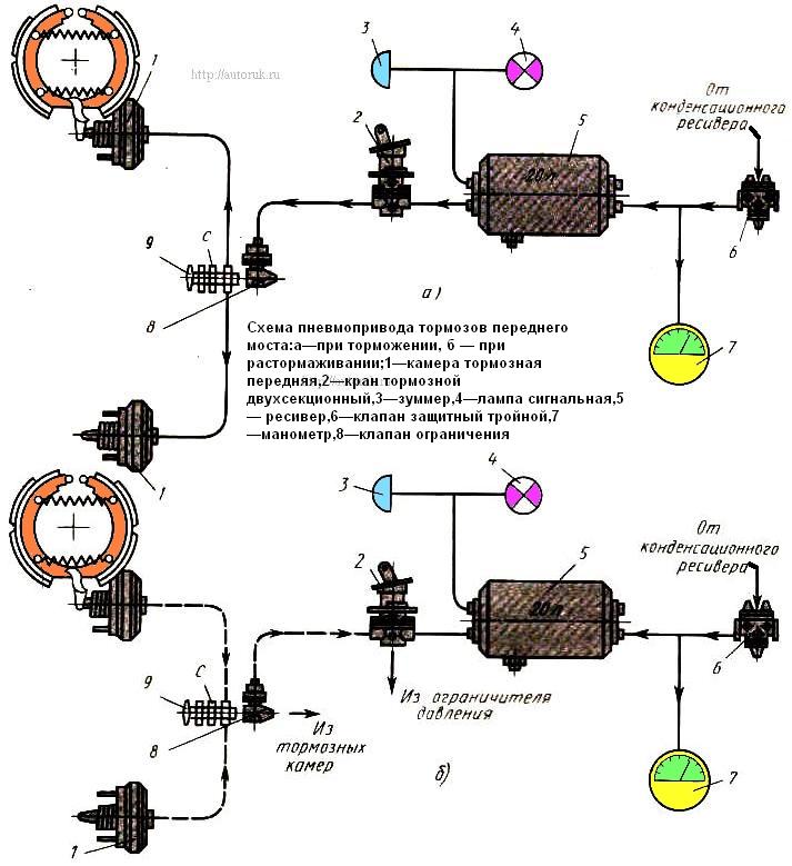
Design and operation of service brake pneumatic actuators
The service brake pneumatic drive is divided into two circuits: I brakes the wheels of the front axle, II brakes the wheels of the rear bogie.

The front axle brake pneumatic drive (circuit I) consists of a part of a triple protective valve 6, a receiver 5 with a capacity of 20 liters with a condensate drain valve and a pressure drop sensor, the upper part of a two-pointer pressure gauge 7, the lower section of a two-section brake valve 2, control valve 9 C, pressure relief valve 8, two brake chambers 1 type 24, front axle brakes, pipelines and hoses between these devices.
When the pressure in the receiver drops below 450 kPa, the pressure drop sensor is triggered and turns on the sound signal in the cab and the signal light of this circuit on the instrument panel.


