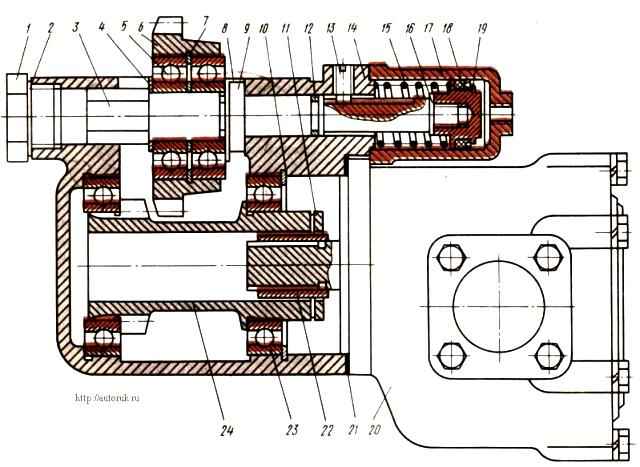
The power take-off with an oil pump is designed to take power from the gearbox and is attached to its crankcase on the right side
Between the flanges of the power take-off housing and the gearbox, gaskets are installed, which are used to regulate the engagement of the gear wheels
If gaskets are replaced, their overall thickness must be maintained.

In the crankcase 14 the driven gear 24 is located in ball bearings 23.
On axis 3, on ball bearings 5, nut 9 and washer 8 with a bending tendril, the intermediate gear 6 is fixed.
The axis is kept from turning by set screw 13.
When assembling, the screw is screwed into the crankcase until it stops at the bottom of the groove on axis 3, and then unscrewed 1.5 turns and uncorked. This allows the axis to move in the longitudinal direction.
The end of the axle with a piston 19 attached to it with a cuff 18 enters the body of the pneumatic cylinder 17.
In the initial position, the axis is held by spring 15. Oil leakage from the cavity of the box into the cavity of the pneumatic cylinder is prevented by ring 12.
To connect the driven gear 24 to the pump shaft, a half-coupling 22 is used, which is connected to it through a compensator 11.
This connection prevents possible distortions of the axis of rotation of the driven gear and the pump shaft when installing it on the power take-off.
In the initial position, the intermediate gear is in constant engagement with the gearbox gear.
When compressed air is supplied to the pneumatic cylinder body, the intermediate gear moves to the left and its ring gear engages with the driven gear ring.
Torque from the driven gear is transmitted to the pump shaft.
The power take-off can only be turned on with a pressure of at least 500 kPa in the pneumatic system and with the clutch disengaged.


