The car frame is stamped, riveted, consists of two channel-section spars, variable in length, connected by cross members
In the front part, the frame is equipped with a front buffer with two towing forks.
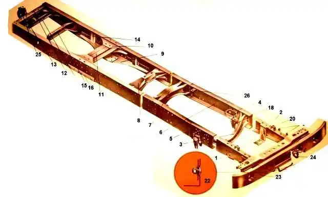
On the rear cross member of the frame of the KamAZ-5320, KamAZ-53212 vehicles there is a towing device with elastic rubber elements that provide double-sided shock absorption.
On the rear cross member of the frame of the KamAZ-5410, KamAZ-54112 and KamAZ-55111 vehicles there is a rigid towing loop without a rubber shock absorber, designed for towing a faulty vehicle over a short distance.
It cannot be used to permanently tow a trailer.
On KamAZ-55111, KamAZ-53229 vehicles the towbar is installed on the rear cross member of the frame, on KamAZ-65115 - on a subframe fixed to the rear of the frame.
KAMAZ vehicles of various models and configurations have different frames: long depending on the base; number and design of crossbars; reinforcing linings and their design; brackets and their position.
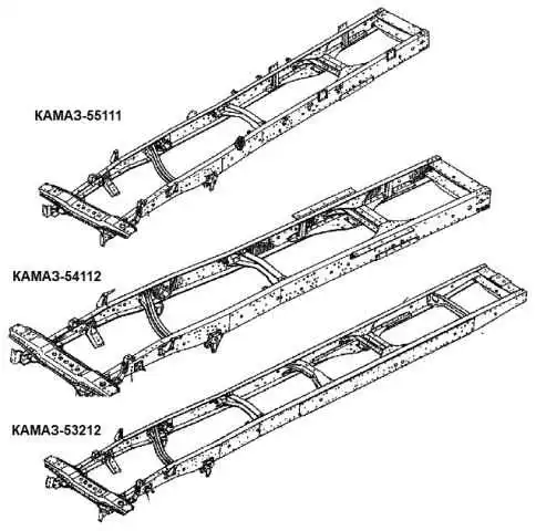
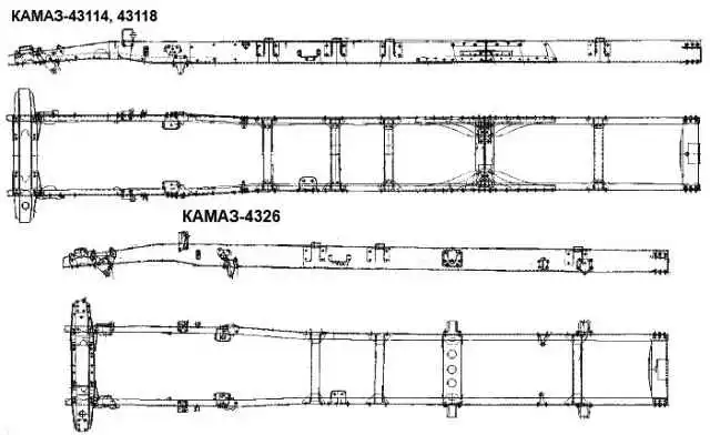
Individual frame samples are shown in the figure
The spars are made of low-alloy strip steel 8 mm thick. Maximum spar section 262x80 mm.
Cars have different frame lengths depending on the base. The frame of the KamAZ-53212 vehicle has reinforcing linings of the side members in the area of the fifth cross member.
The brackets for the power unit supports, cab supports and front suspension are connected to the frame parts with rivets and bolts and nuts.
The towing device of the car consists of a hook, the end of which passes through holes in the rear cross member of the frame, which has an additional reinforcement.
The end of the hook is inserted into a massive cylindrical body, closed on one side with a protective cap and on the other with a body cover.
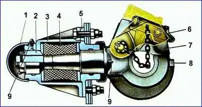
Rubber elastic element (buffer) 4, which softens shock loads when starting a car with a trailer and when driving on uneven roads, is located between two flanges.
A latch is installed on the axis passing through the hook, locked with a pawl 6, which prevents the trailer drawbar from disengaging with the hook.
When assembling the towbar, nut 2 must be screwed all the way into the flange without applying additional tightening force.
After this, turning nut 2, you need to align the slots in it with the hole at the end of the hook, and then install the cotter pin. When combining holes, axial movement of up to 0.5 mm is allowed.
During vehicle operation, nut 2 cannot be used to regulate the axial movement of the hook, since screwing the nut increases the axial movement of the hook.
If axial movement of the hook occurs after long-term use of the vehicle, you should disassemble the towbar and, if necessary, straighten the flanges and replace worn parts.
When shrinking the rubber buffer, it is necessary to install additional ring gaskets between the flanges and the rubber buffer, then tighten the nut, tighten it and put the protective cap 1 in place.
In order to couple a tractor to a trailer you need:
- - brake the trailer with the parking brake system;
- - open the beech lock sire hook;
- - install the trailer drawbar so that the coupling eye is at the level of the car’s tow hook;
- - carefully back the car until the towing hook stops in the trailer coupling eye;
- - place the hitch loop on the towing hook and close the lock;
- - insert the trailer plug into the car socket;
- - connect the hose heads of the trailer pneumatic system with the corresponding heads of the car pneumatic system;
- - connect the trailer to the car with a safety rope or chain;
- - open the disconnect valves of the pneumatic drive of the trailer brake systems installed on the vehicle (single-wire or two-wire circuit);
- - release the trailer using the parking brake system.
To improve maneuverability when towing a trailer, remove the rear buffers from the vehicle.
Maintenance
During daily maintenance, you should check the condition of the towbar by external inspection. Pay special attention to the presence of the latch pin.
At service 2:
- - check the free axial travel of the towing device hook, which should not exceed 6.5 mm;
- - use two grease nipples to lubricate the stem and nut of the towbar hook;
- - tighten the nuts of the bolts securing the fuel tank brackets.
At service C:
- - check the condition of the frame by external inspection. The presence of cracks and traces of corrosion on the flanges of the side members and cross members are not allowed;
- - check the presence of all rivets; if missing, install a bolt and nut.
Repair
Main frame defects:
- - bent side members and cross members;
- - cracks in the side members along the holes for the rivets securing the rear engine mount brackets (Figure (a));
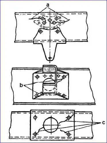
- - cracks along the holes for the rivets fastening the cross member bracket No. 3 to the spar (Figure (b));
- - cracks in the rear cross member along the holes for the towbar mounting bolts (Figure (c);
- - fatigue cracks;
- - weakening of rivet connections;
- - violation of frame geometry
Editing the frame, side members and cross members
Deflections and distortions of the frame are determined by external inspection, as well as using a ruler, feeler gauge and various templates made in the form of a square according to the frame design
The frame must be straightened in a cold state using hydraulic jacks or clamps; as an exception, straightening can be done with a sledgehammer using mandrels and supports.
The support should be massive and fit tightly to the surface in the editing area
If the defect cannot be corrected on the assembled frame, remove the part and correct it separately
Repair of spars and cross members with cracks
We weld cracks in the following order:
- - places on the frame parts that have cracks and need to be welded are cleaned of paint, dirt, oil and other contaminants to a metallic shine;
- - the visible end of the crack is determined using a 4x magnifying glass;
- - we cut the edges for the weld to the depth of the crack and to a length exceeding the length of the crack by at least 20-30 mm on each side.
When a part breaks through the full thickness of the metal, we cut from one side to a depth of ¾ of the metal crack.
Drill the cracks along the edges with a drill with a diameter of 5-6 mm;
The discrepancy between the surfaces of the welded edges is allowed no more than 0.5 mm
- - weld the crack. We maintain the shapes and dimensions of the seam in accordance with the requirements of GOST 5264-80. Use electrodes of type E46A GOST 9467-75 with coating UONI 13/45 or 13/55.
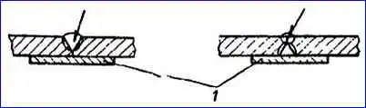
If there is a through crack, weld on both sides on copper lining 1 (picture).
After welding, we clean the seam, the reinforcement of the seam after welding should be 1-1.5 mm, in the place where the reinforcing lining is installed, we clean the seam flush with the base metal
- - strengthen the thermally affected zones with peening using a hammer until small scales appear, cover with primer type FL and GF twice;
- - place a reinforcing pad on the weld.
Make the reinforcing pad from the metal used for the manufacture of Zheronov, steel 15GYUT TU 14-1-2366-73 and 22G2TYU TU 14-1-2092-77.
Cut the linings from parts of rejected KamAZ vehicle frames. Clean the contours and fit them tightly in place
The thickness of the overlays should be equal to the thickness of the part being repaired and 20-30 mm longer than the crack on each side.
The width of the overlay should cover the crack by at least 70-80 mm on each side
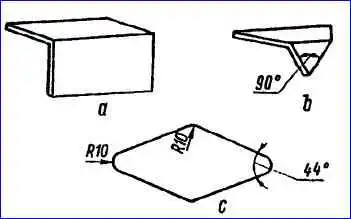
Use rectangular (Figure a), triangular (Figure b) and diamond-shaped (Figure c) overlays
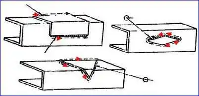
The seams of rectangular reinforcing overlays should only be longitudinal; for triangular and diamond-shaped overlays, apply the seams along the contour of the overlay, starting from the vertical wall towards the shelves (Fig)
Install the overlay from the inside of the part being repaired; if such installation is not possible, it is permissible to install the overlay from the outside.
When installing a cover on a crack that extends to the edge of a part, make it longer than the part by the thickness of the metal.
When installing an overlay on a crack running from the hole to the edge of the part, overlap the edge of the hole by 20-30 mm
After completing the welding work, clean the seam from slag
Repair of rivet joints
Rivet joints are checked by inspection and tapping. We cut off loose rivets by hand
If the holes for rivets are worn more than 1 mm from the nominal diameter of the hole, weld on a copper lining and drill out to the nominal size
Rivet diameter – 12 mm – nominal hole diameter 13 mm;
Rivet diameter – 16 mm – nominal hole diameter 17 mm.
Before riveting, fit the parts tightly together.
Extension by riveting is unacceptable. For riveting frames, use rivets with a diameter of 12 and 16 mm
Recommended rivet material – steel 08KP GOST 1050-74
The length of the rivet is determined by the following formula: L = a + 1.5 d (mm), where a is the thickness of the package of riveted parts (mm); d – rivet diameter (mm)
The riveting should only be cold
Distortions, cracks and tears on the edge of the rivet heads are not allowed
It is possible to replace rivets with bolts with self-locking nuts and spring washers.
A tightened bolted connection should ensure that the bolt exits the nut by 2-3 threads of the bolt thread
Requirements for a repaired frame
Longitudinal displacement of the side members relative to each other is unacceptable
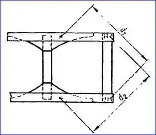
The difference in cross diagonals (d1 – d2) (fig) between the rear cross member mounting holes in the lower flange of the side member and the holes for the rear axle buffer is allowed no more than 3 mm
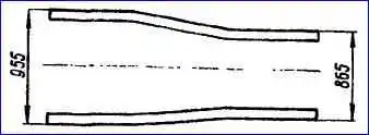
The width of the frame should not deviate from the nominal size (Fig.) in the areas between the crossbars by more than 4 mm, and in the areas where the crossbars are installed - by 2.5 mm
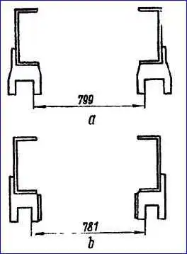
The dimensions between the inner cheeks of the front suspension brackets (Fig.) should not deviate from the nominal by more than 4 mm
The curvature of frame parts should not exceed 2 mm over a length of 1 m; for a spar, the total curvature should not exceed 6 mm over the entire length of the spar
Alignment must be ensured in the front brackets of the front suspension (a stepped rolling pin with a diameter of 40 mm must pass through both holes of one of the brackets and a 39 mm diameter through both holes of the other bracket at the same time).
Welds should not have cracks, pores, cavities in the directional metal and undercuts in the base metal.
Fastening joints must ensure a tight fit of the surfaces of the connected parts at a radius of at least 1.5 times the diameter of the rivet stem relative to its axis; a 0.1 mm probe should not pass between the connected parts
After repair, the frame has been repaired dig with FL type soil.
Repair of towing device
When repairing the towbar, you cannot use nut 2 to adjust the axial travel of the towing hook, since tightening and unscrewing the nut leads to an increase in the axial travel of the hook.
If axial movement of the hook occurs, you need to disassemble the towing device and, if necessary, straighten the flanges and replace worn parts.
If shrinkage of the elastic element occurs, install additional ring gaskets between the flanges and the elastic element, tighten nut 2, tighten it and put cap 1 in place.
If the hook mouth is worn to a size greater than 55 mm, replace the hook.
When assembling the device, screw nut 2 all the way into the flange without applying additional torque, then align the slots in the nut with the hole at the end of the towing hook and install the cotter pin
When combining holes, an axial movement of up to 0.5 mm is allowed.
The surface of the trailer hitch must be flat and smooth.
If a worn-out hinge is repaired by welding metal, thoroughly clean the hinge to give it a geometrically correct shape, otherwise the hinge may become jammed in the towing hook jaw and the jaw may break when turning the road train.
It is not permitted to operate a towbar with a 48 mm diameter opening with a coupling loop made from a rod with a diameter of more than 43.9 mm.