Wheel arrangement. KamAZ vehicles with glued 6X4 formula include two single front steered wheels, four double rear drive wheels
The front wheels of KamA3 cars are discless with spoke hubs, with split rims and pneumatic tires with a universal tread pattern.
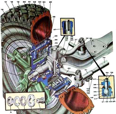
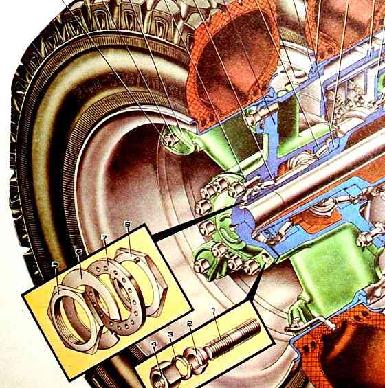
Front axle with wheel: 1 - steering knuckle; 2 - bearing nut; 3 - lock washer of the bearing nut; 4 - lock washer of the lock nut; 5 - lock nut; 6 - hub cover; 7,12, 43, 48, 72 - bolts; 8, 33, 49, 73 - spring washers; 9 - gasket; 10.19 - bearings; 11,15, 32, 35, 45, 57, 68 - nuts; 13 - hub; 14 - hairpin; 16 - clamp; 17 - lock ring; 18 - side ring; 20 - thrust ring; 21 - cuff ring; 22 - front brake oil catcher; 23 - brake drum; 24 - brake pad; 25 - wheel rim; 26, 54 - cuffs; 27 - safety valve; 28 - brake guard; 29 - plug; 30 - caliper; 31 - wedge pin; 34 - steering knuckle stop; 36 - safety valve spring; 37 - longitudinal thrust; 38 - bipod thrust lever; 39 - front axle beam; 40 - steering knuckle lever; 41 - steering linkage rod; 42 - transverse thrust; 44 - washer; 46 - camera; 47 - tire; 50 - top cover; 51 - key; 52 - kingpin; 53 - half ring of the oil seal; 55, 67 - cotter pins; 56, 70 - ball pins; 58, 66 - protective pads; 59, 65 - upper liners; 60, 71 - lower liners; 61 - spring; 62 - threaded cap; 63 - lock washer; 64 - oiler; 69 - lining clip
The front wheel (Fig. 1) consists of a hub, rim and tire.
In the center of the hub there is a cavity in which sockets for installing bearings and hub cuffs are located.
The hub has five spokes, evenly spaced around the circumference.
The ends of the spokes end in conical supports designed to fit the conical surface of the rim.
The 28° cone angle provides, when tightening the nuts, the frictional force necessary to securely connect the rim to the hub and prevent it from turning when braking.
The studs securing the rims to the wheel hubs have a right-hand thread.
In the body of the hub between the spokes there are five holes intended for the brake drum mounting bolts.
The bolt nuts are self-locking.
To reduce tire wear and improve vehicle stability and controllability, the hub assembly with the brake drum is balanced.
Permissible imbalance 700 Nm.
To eliminate imbalances in production, the heaviest part of the hub and drum assembly is first determined, and then a weight is welded to the outer surface of the brake drum from the opposite side.
The mass of the load is determined by the magnitude of the imbalance being eliminated.
The wheel rim with a conical landing shelf is dismountable. It consists directly of a rim, a lock ring and a bead ring.
The rim flange on one side ends with a bead, on the other side - with a shaped section designed for fitting on the conical surfaces of the spokes and placing the bead and lock rings.
The locking ring is split. It is made of a special steel profile. The side ring is also steel.
The tire is pneumatic, tubed, with a radial cord and a universal tread pattern.
Tire marking 260-508Р, which means: 260 is the profile width of the inflated tire in mm, 508 is the outer diameter of the rim, P is a radial tire.
The tire and rim assembly is balanced relative to the conical surface and the end of the rim.
Permissible imbalance 0.3 Nm. Imbalance is eliminated by installing balancing weights.
The number of weights, depending on the imbalance being eliminated, may be different, but should not exceed five. When installing the weight, impacts on it and the spring must be avoided.
The load must be pressed tightly against the lock ring, the protrusion of one load relative to adjacent ones should not exceed 3 mm.
The rear wheels of KamAZ 6X4 vehicles are also discless. The inner wheel rim is mounted on the conical surface of the rear hub spokes.
The distance between the tires of dual wheels is ensured by a spacer spacer ring, which is corrugated to increase rigidity.
This ring also transmits the tightening force of the nuts and clamps securing the outer wheel to the inner wheel.
The clamps of the rear wheels differ from the clamps of the front wheels, since they have a bevel, which at the same time Precisely centers and clamps the outer wheel rim.
The hubs rotate on tapered bearings mounted on the axles of the drive axles
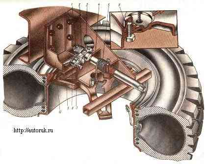
Spare wheels for vehicles with a 6X4 wheel arrangement (except for the KamAZ-5511 dump truck) are installed in a horizontal position above the right side member on bracket 10 (Fig. ), which is secured with five bolts to the frame side member.
The mechanism for raising and lowering the spare wheel is installed on the same bracket.
The gate shaft 4 is prevented from turning in the opposite direction by a ratchet 3 and a latch 8, which is constantly pressed against the ratchet by a spring 7.
To lift the wheel, the shaft is rotated by the square shank with a wheel wrench, cable 5 is wound around the shaft and lifts support 9 along with the wheel. In the raised position, the wheel is fixed with nut 6.
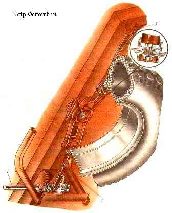
On KamAZ-5511 dump trucks, the spare wheel is mounted on the front side of the platform.
The wheel is raised and lowered using mechanism 1 (Fig. 4) with cable 2, which is passed through block 3.
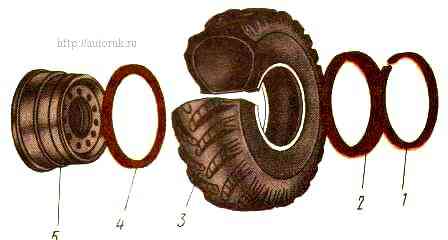
On off-road vehicles with a 6X6 wheel arrangement, all wheels are single, which reduces the resistance to vehicle movement. Disc wheels, with a toroidal surface of the rim flanges 5 (Fig.).
They are equipped with two bead rings 2 and 4, a locking ring 1 and a wide-profile tire 3 with an all-terrain tread pattern.
The model of the tire used is IP184, size 1220X400—533, which means: 1220 mm is the outer diameter of the tire, 400 mm is the profile width, 533 is the outer diameter of the rim.
The conical surfaces of the rim and beads ensure a tight fit of the tire, which allows you to operate at reduced air pressure. The wheels are secured to the hubs with ten studs and nuts.
The wheel hubs on the axle axles of cars with a 6X6 wheel arrangement are secured in the same way as the front wheel hubs of cars with a 6X4 wheel arrangement: with a bearing nut and a locknut, between which two washers are installed to prevent the nuts from self-loosening.
The centralized pneumatic system of KamAZ-4310 vehicles allows you to adjust the tire pressure from the cab within 80-320 kPa, depending on road conditions.
The spare wheel on this vehicle is installed behind the cab in a special holder that has a mechanism for lowering and lifting the wheel with a hydraulic drive.
To remove the spare wheel, you need to disconnect the tightening screws, set the handles on the pump to the “Lower spare tire” position and lower the wheel.
To lift the spare wheel, install it in the folding bracket of the holder and, by swinging the pump handle in the “Spare wheel lift” position, lift the wheel and secure it with tightening screws.
The position of the handles for raising and lowering the spare tire is shown on the label on the pump.
On KamAZ-43105 vehicles, the spare wheel holder is installed on the inside of the front side of the platform. A removable winch is provided to lift the spare wheel.
")

")
")
")
")
")
")
")