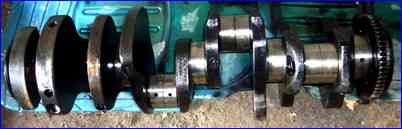
The crankshaft is made of high-carbon steel by hot stamping and strengthened by nitriding or hardening of the connecting rod and main journals with high-frequency currents.
It has five main bearings and four crankpins, which are interconnected by cheeks
The crankpins of the shaft have cavities closed with plugs.
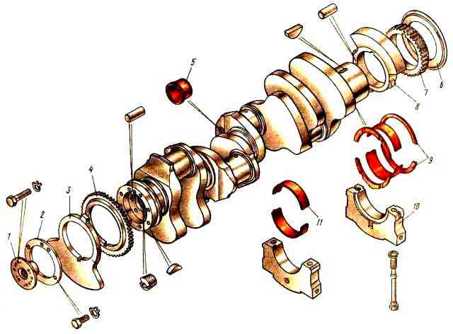
In the cavities, the oil is subjected to additional centrifugal cleaning.
The cavities of the connecting rod journals communicate through inclined holes drilled in the shaft cheeks with transverse channels in the main journals.
On the cheek, toe (front end) and shank (rear end) of the crankshaft there are counterweights of the balancing system; on the cheeks they are made as one piece with the crankshaft, on the toe and shank they are pressed during assembly and secured with a segment key.
On the toe of the crankshaft there is a drive gear for driving the oil pump, and on the shank there is a timing gear assembled with an oil deflector.
In the end part of the crankshaft nose there is a hole for installing the power take-off coupling half, in the end part of the shank there are two holes for pressing in the flywheel fixing pins, an axial hole for the support bearing of the gearbox input shaft and threaded holes for the flywheel mounting bolts.
The shaft is secured against axial displacements by four thrust steel-aluminum half-rings installed in the recesses of the block and the rear main support cover.
The crankshaft shank is sealed with a reinforced rubber cuff, pressed into the flywheel housing, and an oil deflector.
Main and connecting rod bearings are made in the form of replaceable thin-walled split liners, which are installed with interference into precisely machined cylindrical seats - beds.
The crankshaft main and connecting rod bearing shells are made of steel strip coated with a layer of lead bronze and a thin layer of lead alloy.
The upper and lower crankshaft main bearing shells are not interchangeable.
The upper main bearing shells differ from the lower ones by the presence of holes for oil supply and an annular groove for its distribution.
The upper and lower crankshaft connecting rod bearing shells are interchangeable.
To prevent rotation and axial movement of the liners in the sockets, the edges of the liners have extruded edges that fit into the corresponding grooves made in the beds of the block and connecting rod, as well as in their covers.
As the crankshaft journals wear out, they can be ground four times; the liners are available in seven repair sizes (table), since the holes in the block and connecting rods can be bored for the liners to the repair size.
Repair dimensions of crankshaft journals and bearing beds

Stamps of the repair size and diameters of the crankshaft journals and beds in the block or connecting rod are applied to the back side of the liner not far from the plane of the connector.
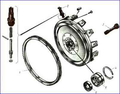
The flywheel (Fig. 3) is necessary to accumulate kinetic energy during the power stroke and rotation of the crankshaft during auxiliary strokes, as well as to remove the piston from dead points and reduce the unevenness of shaft rotation.
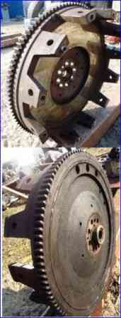
The flywheel is cast from special gray cast iron. It is secured to the rear end of the crankshaft with eight 3 alloy steel bolts.
Precise fixation of the flywheel on the crankshaft is achieved using two locating pins pressed into the end of the crankshaft.
A ring gear 1 is pressed onto the machined cylindrical surface of the flywheel, intended for connection with the starter shaft gear when starting the engine.
The clutch is installed at the rear end of the flywheel.
To regulate the engine, there is a groove on the flywheel for flywheel clamp 2 and 12 holes for turning the crankshaft with a crowbar.
")

")
")
")
")
")
")
")