The two-line bypass valve (Fig. 1) is designed to control one actuator (spring energy accumulator) through one of two independent circuits to choose from
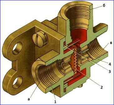
It consists of a body 1 with a cover 3, a seal 2 and two seats in them.
Valve terminal I is connected to the accelerator valve line, terminal II is connected to the spring energy accumulator line, terminal III is connected to the emergency brake release valve line.
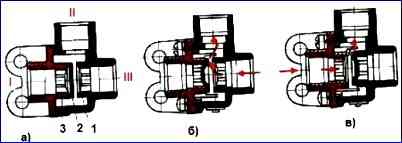
When the car is released using a manual brake valve (Fig. 1.b), compressed air from the parking brake receiver is supplied through the accelerator valve to terminal I, pressing seal 2 to the seat of cover 3, and then through terminal II enters the cylinders of spring energy accumulators.
When the car is released using the emergency brake release valve (Fig. 1.c), compressed air is supplied to terminal III and seal 2 is pressed against the seat in housing 1.
The car is braked by releasing compressed air from spring energy accumulators, while seal 2 remains pressed to the seat and air freely passes through terminal II to terminal I or III.
When compressed air is simultaneously supplied to terminals I and III, seal 2 can occupy a neutral position.
Repair of double-line bypass valve
Disassembly of the valve
Unscrew screws 6 (Fig. 3) with washers 5 securing cover 4 to body 1
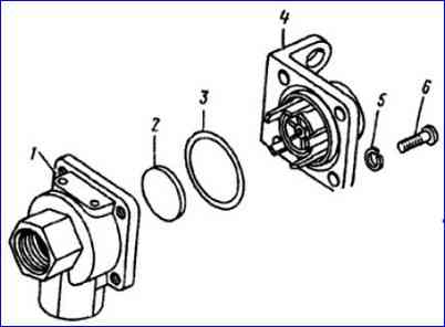
Disconnect the cover and valve body, remove ring 3 and seal 2
We wash the valve parts in diesel fuel, blow with compressed air and check the technical condition
Assemblyof the valve
Install ring and seal 2 into cover 4 and body 1
Insert fastening screws 6 with washers 5 into the holes of the cover and body and screw them in
We test the valve for operability and tightness
Test order
We connect device 6 according to the diagram shown in Figure 4
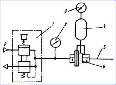
Open and close precision control valve 1 several times
Using precision control valve 1, we set pressure on pressure gauges 2 and 3 to 19.6 kPa (0.2 kgf/cm 2), while air leakage from device 6 is allowed (3 cm 3 /min) from the free end of pipeline 5.
At a pressure above 39.3 kPa (0.4 kgf/cm 2), air leakage is not allowed
When air is quickly released from receiver 4 (5 l) to a pressure of 19.6 kPa (0.2 kgf/cm 2), complete tightness of device 6 must be maintained.
At a pressure below 19.6 kPa (0.2 kgf/cm 2), air leakage from the free end of the pipeline 5 is allowed
Connect device 6 according to the diagram, swapping pins 1 and 2, repeat the test.