Removing the high-pressure fuel pump
To remove the high-pressure fuel pump:
- - disconnect the manual control cables for the engine stop lever and the governor control lever, the fuel supply control rod, the fuel supply lines to the pump, the outlet, drain lines and the line from the fine fuel filter, the oil supply pipe to the pump, the oil drain pipe;
- - unscrew the two bolts of the driven half coupling (to unscrew the bolts, move them to a convenient position by turning the crankshaft with a crowbar by the holes on the flywheel through the clutch housing hatch);
- - disconnect the lines supplying fuel to the pin spark plugs, the high-pressure lines (remove them), the air supply pipe to the auxiliary brake system valve;
- - unscrew four fuel pump mounting bolts;
- - remove the pump.
To install the high-pressure fuel pump:
- - turn the crankshaft to the position corresponding to the start of fuel injection in the first cylinder (the lock is engaged with the flywheel); while the keyway of the drive leading half coupling should be:
- - at the bottom, for engines mod. 740.11-240 and mod. 740.14-300;
- - in a horizontal position on the left, when viewed from the flywheel side for engine mod. 740.13-260;
install the pump on the engine, aligning:
- - marks on the pump body and fuel injection advance coupling, for engines mod. 740.11-240 and mod. 740.14-300;
- - installation mark on the flange of the driven half coupling with the pointer on the fuel injection pump body for engine mod. 740.13-260;
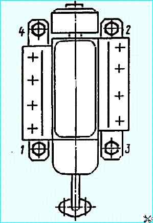
- - tighten the pump mounting bolts as shown in the figure;
- - without disturbing the relative position of the marks, tighten the upper bolt of the driven half coupling of the drive, move the lock into the small groove, turn the crankshaft one revolution and tighten the second bolt of the driven half coupling;
- - install the crankcase hatch cover clutch;
- - connect the high-pressure pipes, the oil supply pipe to the high-pressure fuel pump and the oil drain pipe, the air supply pipe to the auxiliary brake system valve, the low-pressure pipes, the fuel supply control rod, the manual control cables of the stop lever and the governor control lever.
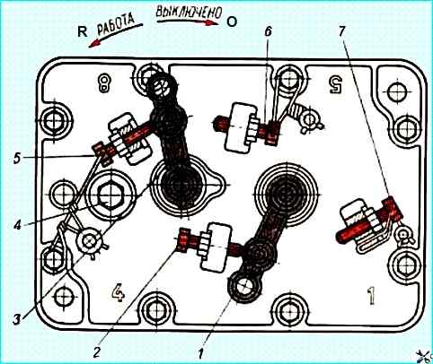
After installing the high-pressure fuel pump, start the engine and adjust the minimum idle speed with bolt 2 (Fig. Fuel injection pump regulator cover), which should be 600±50 min -1.
When repairing the high-pressure fuel pump:
- - replace the pump body with cracks and stripped main threads;
- - plunger bushing defects include chipping and flaking of metal at the holes, scoring, scratches, wear of the working surface, an increase in the diameter of the inlet and cut-off windows, cracks and weakening at the landing sites (chipping, flaking of metal and cracks are irreparable defects).
Wear of the working surface of the plunger bushing measure with an accuracy of 0.001 mm, ovality, taper and enlargement of the bushing hole with a micrometer or indicator device for measuring internal surfaces with a division value of up to 0.001 mm and cone gauges;
- plunger defects include metal chipping and scratches on the working surface, wear of the working surface and cracks.
Detect the distortion of the plunger geometry with a minimeter with an accuracy of 0.001 mm when setting its pointer to zero according to the original sample or with a gauge in the form of a cone bushing;
- check the gap size in the plunger pair on a pressure test bench with a falling weight.
Before testing, thoroughly rinse the parts of the pair in filtered diesel fuel.
Install the plunger pair in the bench seat, the plunger - in the position of maximum feed.
Fill the above-plunger space with filtered diesel fuel.
Install the sealing plate on the end of the bushing, clamping it with a screw, then release the weight latch. Under its action, fuel will gradually begin to be squeezed out through the gap in the steam - chem the larger the gap, the faster.
The value of the load on the plunger should correspond to the value of the fuel pressure of 19.1-20.1 MPa (195-205 kgf/cm 2).
Full lifting of the plunger to the moment of cutoff under the action of the load, accompanied by squeezing out the fuel through the gap between the sleeve and the plunger, should occur in no less than 20 s.
Install the plunger pair with a plunger lifting time to cutoff of more than 40 s, moistened with filtered diesel fuel, in a vertical position on the end of the sleeve, having previously placed a sheet of clean paper.
After a five-minute hold, when lifting the pair by the plunger tail, the sleeve should fall from the plunger under the action of its own weight;
- The plunger pusher is installed in the hole of the pump body with a gap of 0.025-0.075 mm.
The maximum permissible gap during operation is 0.2 mm. Measure the outside diameter of the plunger pusher with a micrometer or a caliper;
- in the assembly unit pusher roller - roller bushing - roller axis, the main defect is wear of the mating surfaces.
The total clearance in the mating 0.022-0.087 mm, the maximum permissible is 0.3 mm (measure with an indicator head).
If the wear exceeds the specified limit, disassemble the pusher and repair, while taking measurements separately.
The maximum permissible clearance for wear of surfaces in the roller axis - roller bushing connection is 0.12 mm, in the roller bushing - pusher roller connection 0.18 mm.
Measure the outer surfaces of the parts with a micrometer, the inner ones - with a bore gauge with an indicator.
- on the surface of the camshaft, do not metal chipping, scoring, thread stripping, and traces of corrosion are allowed.
The maximum permissible height of the cam profile is not less than 47.7 mm (the height of the cam profile according to CD is 47.95-48.05 mm).
Make measurements with a 47.7 gauge; the diameter of the journals for the inner rings of the bearings must be at least 30.0 mm (according to CD 30.002-30.011 mm), the interference fit along the sealing edge of the cuff is at least 0.5 mm;
- no cracks, dents, or traces of corrosion are allowed on the surface of the discharge valve.
Valve wear is manifested in the loss of tightness along the sealing cone, in the valve jamming in the seat.
Use a 10x magnifying glass to detect defects.
If tightness is lost, jointly grind the seat and valve along the cone with GOST 3647-71 paste; if the valve jams in the seat, wash the parts with gasoline or diesel fuel.
If the jamming is not eliminated, replace the pair;
- the maximum permissible gap in the mating pin rack lever - rack groove 0.18 mm (according to CD 0.025-0.077 mm), maximum permissible clearance in the mating axis of the pivot bushing leash - fuel pump rack groove 0.3 mm (according to CD 0.117- 0.183 mm).
Use a bore gauge to measure the grooves.
When repairing the speed controller:
- replace the upper and rear covers of the controller if there are cracks on them.
If the mesh oil filter in the rear cover of the controller is clogged, blow it out with compressed air. If the filter is defective, replace it.
The operating oil flow rate through the filter should be at least 1.6 l/h at a pressure of 98.1-294 kPa (1-3 kgf/cm 2);
- to determine the suitability for further operation, inspect and measure the regulator weight holder assembly with weights without disassembling, since when pressing out the part, it can be damaged and the pairing of the weights, which are selected with a static moment difference of no more than 196 kPa (2 kgf/cm 2), will be disrupted.
Partially or completely disassemble the assembly unit only if wear exceeds the permissible limit, or parts are destroyed.
The gap between the regulator spring lever and the lever axis pressed into the pump body should not exceed 0.3 mm
When repairing the low-pressure pump and the fuel pre-priming pump:
- - replace the low-pressure pump and the fuel pre-priming pump if there are cracks in the housing, fractures, mechanical damage, corrosion leading to loss of mobility of the mating parts;
- - when disassembling and assembling the low-pressure pump, remember that the piston and the pump housing are a precisely matched pair and cannot be disassembled.
The pump is disassembled and repaired only if it does not provide the required characteristics;
- - pay special attention to the condition of the low-pressure pump rod - bushing assembly unit, since the amount of fuel flowing into the camshaft cavity depends on the amount of wear in the mating joint.
The gap in this mating joint should not exceed 0.012 mm.
Check the gap size without removing the bushing from the pump body, by determining the time it takes for the air pressure to drop from 490 kPa (5 kgf/cm 2) to 392 kPa (4 kgf/cm 2) in a 30 cm 3 accumulator.
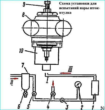
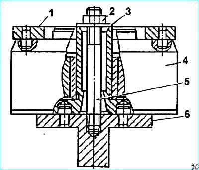
The diagram of the setup for measuring the density of a precision assembly unit is shown in the figure.
Install the pump body 8 in the device, fill the accumulator with compressed air to a pressure of at least 539 kPa (5.5 kgf/cm 2), hermetically disconnect it from the compressed air line and Measure the time during which the pressure in the accumulator drops from 490 kPa (5 kgf/cm 2) to 392 kPa (4 kgf/cm 2).
Compare the obtained time with similar density readings of the reference precision pair, which has a gap in the mating of 0.012 mm.
Replace or repair the pair if its density is less than the reference.
The density of the pair can be checked in a simpler way: pass filtered diesel fuel through the gap between the rod and the bushing.
The volume of fuel leaking through the gap should not exceed 1 cm 3 within 20 minutes.
If the rod - bushing assembly is replaced, clean the thread surface and the end face in the low-pressure pump body from residues glue.
Install the new rod bushing into the pump body using glue based on epoxy resin.
To ensure the strength and tightness of the connection, first degrease the cleaned contact surfaces of the pump body and the bushing with B-70 gasoline.
After tightening the rod bushing to a torque of 9.81 Nm (1 kgfm), check the ease of movement of the rod in it. If necessary, reduce the tightening torque.
Check the pump feed during testing.
Make the test setup according to the diagram: fuel tank - coarse fuel filter - vacuum gauge - fuel pump - pressure gauge - graduated tank.
Connect the elements of the diagram with transparent pipes with an internal diameter of at least 8 mm.
Install taps to create a vacuum at the pump inlet and back pressure at the outlet.
Carry out the test on summer diesel fuel at a temperature of 25-30° C, in the absence of air in the system, make sure the fuel stream in the transparent pipes is clean.
The pump should suck fuel from a tank installed 1 m below the pump.
Pump feed at a camshaft speed of 1100-1300 min -1, vacuum at the inlet fitting 23 kPa (173 mm Hg) and back pressure:
- - 80-100 kPa (0.8-1.0 kgf/cm 2) should be at least 3 l/min for engines mod. 740.11-240 and mod. 740.13-260;
- - 125 kPa (1.25 kgf/cm 2) should be at least 3.5 l/min for engine 740.14-300.
With the outlet valve completely closed and the camshaft speed of 1100-1300 min-1 the pump should create a pressure of at least:
- - 400 kPa (4 kgf/cm 2) - for engines mod. 740.11-240 and 740.13-260;
- - 600 kPa (6 kgf/cm 2) - for engine 740.14-300.
With the inlet valve completely closed and the specified camshaft speed, the minimum vacuum created by the pump should be:
- - 52 kPa (390 mm Hg) - for engines mod. 740.11-240 and 740.13-260;
- - 70 kPa (525 mm Hg) - for engine 740.14-300;
- - check the pre-start fuel pump on a stand with a diagram: fuel tank - coarse filter - fuel pump. The pump should supply fuel from a tank installed 1 m below the hand pump.
Check the pump for leaks by supplying air under the piston at a pressure of 200-300 kPa (2-3 kgf/cm 2) for 5-6 seconds with preliminary wetting of the cavity with diesel fuel.
Use a device to remove the automatic fuel injection advance clutch.
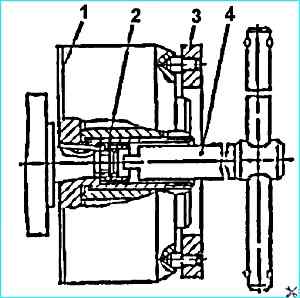
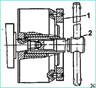
First, unscrew nut 2 (see Fig. Unscrewing the nut securing the fuel injection advance coupling) securing the coupling.
To do this, insert screwdriver 4 into the groove of the nut and, holding coupling 1 from turning with wrench 3, unscrew the nut.
Then, screw in Insert puller 2 into the coupling (Fig. Removing the coupling with a device), remove the coupling.
To disassemble the coupling:
- unscrew the screws from the housing and drain the oil:
- - clamp support 6 (Fig. Disassembling the coupling) of the device in a table vice and install the coupling on it, screw stud 5 into the support, install washer 3 and tighten with nut 2;
- - unscrew housing 5 with key 1 (see Fig. Automatic fuel injection advance coupling);
- - remove leading half coupling 1 with spacers 12, weights 11, springs 8;
- - press out seals 4 and 2.
Considering that the weights are selected based on the static moment, keep them paired for subsequent installation.
To assemble the coupling:
- - press in cuff 4 into the hole of the leading half coupling;
- - install the leading half coupling with a mandrel on the hub of the driven one;
- - install the adjusting linings 6 and springs 8 in the cups 7, cups with springs
- - into the guide holes of the weights, in which they should move freely without jamming.
In any position of the coupling parts, the gap between the profile surface and the spacer should be no more than 0.15 mm.
When the weights are brought to the stop by turning the leading half coupling, one of the gaps should be no more than 0.1 mm, the other is zero.
Adjust the gaps by selecting spacers:
- - press the cuff into the coupling body flush with the inner end surface 2;
- - install rubber sealing ring 14 into the groove of the driven half coupling;
- - screw the housing onto the driven half coupling and tighten to a torque of 314-343 Nm (32-35 kgfm);
- - calk the driven half coupling in three places.
Before installing the housing, ensure equal gaps between the housing and the spring cups with the weights brought together to the stop. The difference in gaps should be no more than 0.2 mm.
After assembly, fill the coupling with engine oil used for the engine.
To disassemble the injector, use the I801.20.000 device.
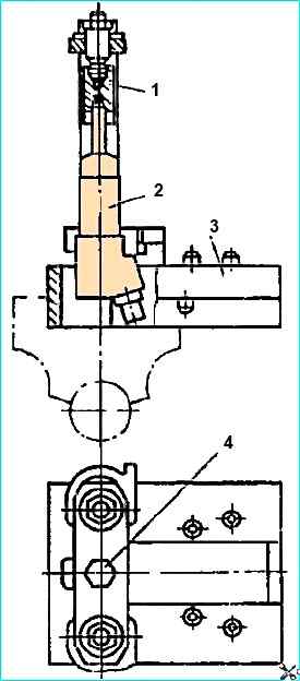
Clamp the frame 2 (Fig. Disassembling the nozzle) of the device in a vice, install the nozzle in the groove of the frame with the sprayer facing up.
When screwing in bolt 4, press the nozzle sprayer with stop 1, then unscrew the sprayer nut with an open-end wrench.
After unscrewing bolt 4, remove the nozzle from the device and disassemble it into parts.
Remember that the body and the needle of the sprayer are selected as a pair and cannot be disassembled. The maximum permissible gap between the body and the nozzle needle is 0.006 mm.
Do not allow the nozzle needle stroke to increase by more than 0.4 mm, the diameter of the nozzle holes of the nozzle should not exceed 0.38 mm.
Unsatisfactory operation of the injectors is caused by a decrease in the pressure at the start of fuel injection, which is explained by the wear of the parts associated with the spring and the shrinkage of the spring, therefore, do not allow the height of the injector spacer to be less than 8.89 mm (according to CD 8.9-9.0 mm).
If scratches and traces of corrosion are found on the spacer (use a magnifying glass with tenfold magnification), replace the part.
Injector defects include spring breakage, clogging and wear of the nozzle holes, needle sticking and wear of its sealing part (causing leakage and poor fuel atomization).
If necessary, carefully clean the nozzle holes of the sprayer with a steel wire of 0.25 mm diameter.
Remove carbon deposits from the outer surface of the sprayer with a wooden block soaked in motor oil or a brass brush. Do not use sharp hard objects or sandpaper.
Before assembly, wash the nozzle body and needle with gasoline and lubricate with filtered diesel fuel, after which the needle, extended from the body by one third of the length of the guide surface, when tilting the nozzle at an angle of 45 ° should smoothly (without jamming) lower to the stop under the action of its own weight.
When assembling the nozzle, tighten the nozzle nut by pressing the nozzle in the I801.20.000 device.
Dimensions of parts and permissible wear, mm
Automatic clutch fuel injection advance
According to CD / Permissible
- Diameter of the hole in the coupling weight 16.032-16.059 / 16.1
- Load axle diameter 15.982-16.000 / 15.86
- Gap between axle and load 0.032-0.077 / 0.24
- Space spacer hole diameter 16.032-16.059 / 16.1
- Drive half coupling pin diameter 15.973-16.000 / 15.9
- Gap between the pin and the hole in the spacer 0.032-0.086 / 0.2
High pressure fuel pump mod. 337-40
According to CD / Permissible
- Plunger pusher hole diameter in pump body 32.000-32.025 / 32.1
- Plunger pusher diameter 31.950-31.975 / 31.9
- Gap between pump body and plunger pusher 0.025-0.075 / 0.2
- Roller bushing inner diameter 11.006-11.024 / 11.04
- Roller axis diameter 10.989-11.000 / 10.93
- Gap between roller axis and bushing 0.006-0.035 / 0.11
- Tappet roller bore diameter 15.000-15.018 / 15.08
- Roller bushing outer diameter 14.956-14.984 / 14.9
- Roller bushing to roller clearance 0.016-0.052 / 0.18
- Bearing inner diameter 29.989-30.001
- Camshaft journal diameter 30.002-30.011 / 30
- Camshaft to bearing clearance 0.000 - 0.001 / 0.003
- Inner diameter Rack lever bushings 7.00-7.03 / 7.1
- Rack lever axle diameter 6.945-6.985 / 6.9
- Gap between axle and bushing 0.015-0.085 / 0.2
- Rack groove width 5.025-5.065 / 5.1
- Rack lever pin diameter 4.988-5.000 / 4.92
- Gap between pin and groove walls 0.025-0.077 / 0.18
- Rack groove width (groove for pivot bushing driver axle) 4.100-4.148 / 4.2
- Axle diameter 3.965-3.983 / 3.9
- Gap between axis and groove walls 0.117-0.183 / 0.3
Speed controller
- Inner diameter of weight sleeve 7.035-7.065 / 7.1
- Diameter of governor weight axis 6.99-7.00
- Gap between weight axis and sleeve 0.035-0.075
- Inner diameter of weight roller 7.023-7.050
- Diameter of roller axis 6.99-7.00
- Gap between axis and roller 0.023-0.060
- Control lever bushing inner diameter 12.000-12.035 / 12.25
- Control lever shaft diameter 11.93-11.98
- Gap between shaft and bushing 0.020-0.105 / 0.4
- Thrust heel hole diameter 8.023-8.050 / 8.1
- Heel axis diameter 7.99-8.00 / 7.90
- Axle to hole gap 0.023-0.060 / 0.2
- Governor spring lever hole diameter 10.013-10.033 / 10.15
- Spring lever axle diameter 9.915-9.965 / 9.85
- Lever axle to hole clearance 0.048-0.118 / 0.3
- Weight holder hole diameter 15.000-15.035 / 15.2
- Weight coupling sleeve sphere diameter 14.60-14.53 / 14.4
- Sphere to hole clearance 0.40-0.50 / 0.8
- Weight coupling lever hole diameter 10.035-10.085 / 10.1
- Governer lever sleeve outer diameter 10.010-10.025 / 9.9
- Gap between bushing and hole in lever 0.010-0.075 / 0.2
- Inner diameter of governor lever bushing 7.00-7.023 / 7.1
- Lever axle diameter 6.940-6.965 / 6.9
- Gap between bushing and lever axle 0.035-0.090 / 0.2
- Right rack groove width 5.100-5.148 / 5.2
- Diameter of weight clutch lever pin 4.992-5.000 / 4.95
- Gap between pin and groove walls 0.100-0.156 / 0.25
- Inner diameter of the push rod bushing 6.000-6.025
- Rod diameter 5.997-6.020
- Gap between the rod and the bushing 0.0027-0.0045 / 0.01
- Pump housing hole diameter 25.000-25.021 / 25.1
- Pump piston diameter 24.98-24.993 24.92
- Gap between the piston and the housing hole 0.007-0.041 / 0.18
- Pusher hole diameter in the regulator cover 19.000-19.023 / 19.09
- Pusher diameter 18.915-18.975 / 18.89
- Pusher to cover clearance 0.025-0.108 / 0.2
- Pusher hole diameter 7.000-7.016 / 7.05
- Roller axle diameter 6.973-6.987 / 6.9
- Axle to pusher clearance 0.013-0.043 / 0.15
- Pusher roller inner diameter 7.023-7.050 / 7.12
- Roller axle diameter 6.973-6.987 / 6.84
- Clearance between axis and roller 0.036-0.077 / 0.28
Tightening torques of threaded connections, Nm (kgcm)
- Injector nipple 78.5-98.1 (8-10)
- Injector nozzle nut. 58.8-78.5 (6 - 8)
- Injector mounting bracket nut 31.4-39.2 (3.2-4.0)
- Injection advance coupling mounting nut 98.1-117.7(10-12)
- Injection advance coupling housing. 314-343 (32-35)
- Oil filler screws on injection advance clutch housing 4.9-10.8 (0.5-1.1)
- High pressure fuel line fastening nut 24.5-44.1 (2.5-4.5)
- Low pressure fuel line fastening bolts to injectors 19.6-24.5 (2.0-2.5)
- Low pressure fuel line fastening bolts to electromagnetic valve 16.7-22.6 (1.7-2.3)
- High pressure fuel pump section fitting 98.1-117.7 (10-12)
- High pressure fuel pump section flange fastening nuts 24.5-43.2 (2.5-4.4)
- Fuel pump drive eccentric fastening nuts, bottom whose pressure is 44.1-54.0 (4.5-5.5)