Repairing the water pump
To remove and disassemble the water pump:
- - drain the coolant from the engine;
- - remove the water pump drive belts;
- - unscrew the three water pump mounting bolts;
- - remove the water pump from the water pipes.
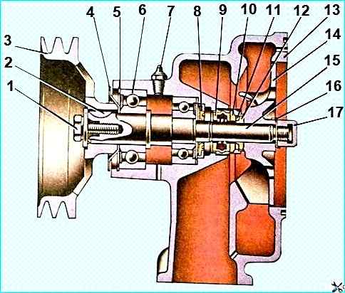
Water pump: 1 - mounting bolt pulley; 2 - key; 3 - pulley; 4 - dust deflector; 5 - retaining ring; 6 - bearing; 7 - oiler; 8 - water pump cuff: 9 - oil seal; 10 - thrust ring; 11 - sealing ring carrier; 12 - sealing ring; 13 - water pump housing; 14 - water pump impeller; 15 - water pump shaft; 16 - lock washer; 17 - cap nut
Disassemble the pump in the following order:
- - bend back the lock washer 16 (see fig. Water pump) and, holding the shaft from turning by the pulley, unscrew the cap nut 17;
- - remove the impeller 14 with a puller;
- - remove the sealing rubber ring 12 with the collar and the thrust ring 10;
- - remove the oil seal 9;
- - unscrew the bolt 1, remove the washer;
- - remove the pulley 3 with a puller;
- - remove the key and dust deflector 4;
- - remove retaining ring 5;
- - remove shaft 15 complete with bearings;
- - remove cuff 8.
During assembly, do not allow foreign particles to get between the surfaces of the rubbing pair of the mechanical seal.
After assembly, check the ease of rotation of the pump shaft (jamming is not allowed).
When repairing a water radiator, radiator defects include damage to tanks and tubes, poor soldering of parts, as well as contamination from the outside and significant scale deposits in the tubes.
Wash the contaminated radiator core from the outside in the direction opposite to the air flow.
Check the tightness of the radiator, for which close the openings of the pipes with plugs, and connect compressed air under pressure of 78.51 kPa (0.8 kgf/cm 2), while the radiator must be filled with coolant.
Tightening torque of the fan hub fastening nut 137.3-196.2 Nm (14-20 kgf-m).
Dimensions of parts and permissible wear, mm
Water pump
Nominal / Permissible
Diameter of the hole in the water pump housing:
- - for front bearing 61.99-62.02 / 62.04
- - for rear bearing 51.99-52.02 / 52.04
- - for oil seal 36.45-36.474 / 36.474
Water pump shaft journal diameter:
- - for front bearing 25.002-25.017 / 25
- - for rear bearing 20.002-20.017 / 20
- - for impeller 15.64-15.675 / 15.64
Impeller hole diameter for shaft journal 15.60-15.635 / 15.62
Pulley hole diameter for shaft journal 24.90-24.923 / 24.94
Fan drive fluid coupling
Nominal / Allowable
Drive shaft:
- - journal diameter for bearing34.973-34.99 / 34.96
- - hole diameter for rear bearing47.010-47.035 / 47.00
Diameter of driven shaft journal:
- for front bearing24.993-25.007 / 24.986
- for rear bearing20.002-20.017 / 19.995
Bearing hole diameter in housing bearing 71.970-72.0 / 72.015
Generator drive pulley shaft:
- - bearing hole diameter 61.970-62.0 / 62.015
- - bearing journal diameter 70.01-70.03 / 70
- - journal diameter under seal 99.930-100.0 / 99.3
To remove and disassemble the fluid coupling:
- - drain the oil from the engine;
- - remove the water pump drive belts and fan impeller, centrifugal oil filter, oil pan;
- - unscrew the front cover mounting bolts to the cylinder block and remove the fluid coupling assembly with the front cover of the block;
- - straighten the tabs of the lock washer of the fan hub fastening nut, unscrew the nut and remove the hub:
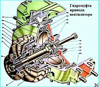
Fan drive fluid coupling: 1 - generator drive pulley; 2 - fan hub; 3 - driven shaft seal bushing; 4 - driven shaft seal; 5, 8 - pulley shaft bearings; 6 - pulley shaft; 7 - pulley shaft seal; 9 - oil deflector; 10 - drive wheel; 11 - plug; 12 - oil supply pipe; 13 - bearing housing; 14 - driven wheel; 15 - drive shaft bearing; 16 - fluid coupling drive shaft; 17 - drive shaft with casing; 18 - fluid coupling driven shaft; 19 - driven shaft rear bearing; 20 - front block cover
- - unscrew the pulley mounting bolts, remove pulley 1 (see fig. Fan drive fluid coupling) with cuff 4 in assembly and sleeve 3 of the cuff;
- - remove the bearing mounting retaining ring;
- - unscrew the bearing housing mounting screws, remove housing 13 in assembly with the bearing;
- - remove the fluid coupling from the front cover of the block;
- - unscrew the drive shaft assembly with the casing mounting bolts to the drive wheel, remove drive shaft 17 in assembly with the casing;
- - remove the driven shaft 18 in assembly with the driven wheel.
After assembly, the drive pulley generator, and the driven shaft with a stationary pulley should rotate freely, without jamming.
To remove and disassemble the thermostat box:
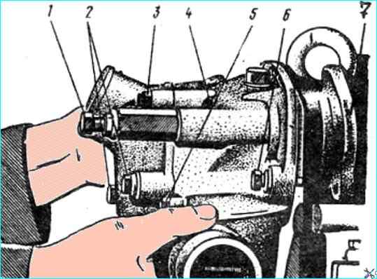
Installing the thermostat box: 1 - generator bar mounting bolt; 2 - box pipe mounting bolts; 3 - pipe; 4 - thermostat box; 5 - bolt; 6 - thermostat box mounting bolt; 7 - connecting flange
- - unscrew bolt 1 securing the generator bar (Fig. Removing the thermostat box):
- - unscrew two bolts 5 securing the box flange;
- - unscrew three bolts 6 securing the box and remove the box;
- - unscrew five bolts 2 securing the pipe, remove the pipe 3. remove the thermostats and inspect them.
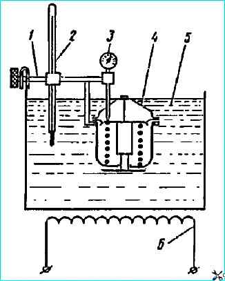
Installation diagram for testing thermostats: 1 - bracket; 2 - thermometer; 3 - indicator; 4 - thermostat; 5 - water bath; 6 - electric heater
To test the thermostats, determine the opening temperature and stroke of valve 5 (see fig. Thermostat) as follows:
- - immerse the thermostat in a heated bath of water (3 l), the level of which should be higher than the thermostat flange (see fig. Thermostat testing setup diagram).
- - after reaching a temperature of plus 70 °C, heat the water continuously at an intensity of no more than 3 °C/min, stirring. Use a mercury thermometer with a division value of no more than 1 ° C;
- - check the indicator for the beginning of the thermostat valve opening - this is the temperature at which the valve stroke will be 0.1 mm.
Thermostats should begin to open at a temperature of 78-82 ° C and fully open at 91-95 ° C. The full stroke of the thermostat valve must be at least 8.5 mm.
During operation, the permissible temperature for the start of opening is 77-83 °C, for full opening - 90 - 96 °C, the loss of valve travel is no more than 20%.
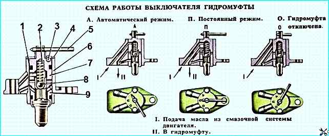
Scheme of operation of the fluid coupling switch: 1 - sealing ring; 2 - spring; 3, 8 - balls; 4 - cover; 5 - lever; 6 - fluid coupling switch housing; 7 - plug; 9 - valve with thermal force sensor
If the fan switch-on temperature is not maintained in the range of 86 - 90 °C, replace the thermal force valve, consisting of a sensor (see Fig. Fluid coupling switch), housing and seat.
To remove and disassemble the fluid coupling switch:
- - unscrew the bolts securing the switch to the branch pipe of the supply pipe, remove the switch;
- - secure the switch by the housing in a vice;
- - remove the cover, take out the plug, spring and ball
- - take out the valve assembled with the thermal force sensor.
The valve and plug should move in the housing without jamming.
On the mating surface the housing should not have marks deeper than 0.05 mm; the surface flatness should not be more than 0.05 mm.
There should be no areas of cavitation destruction or damage on the surface of the sensor housing.
")

")
")
")
")
")
")
")