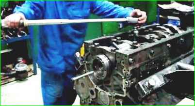
For disassembly, it is recommended to use the P-770 rotary stand, on which the engine can rotate around the vertical and horizontal axis
Before installing the engine on the stand, remove the oil filter with heat exchanger, fan, exhaust manifolds, front support brackets, starter;
- - lubricate the rubbing surfaces of parts, except for those specified separately, with engine oil during assembly;
- - when fastening parts using threaded connections, ensure the appropriate tightening torque;
- - non-metallic gaskets for ease of assembly, if necessary, put with the application of consistent grease to one of the mating parts.
- - Make sure that the gaskets fit evenly to the mating surfaces, are tightly clamped and do not protrude beyond the contour of the mating surfaces;
- - when installing rubber Lubricate the sealing rings and the lead-in chamfers of the mating parts with consistent grease;
- - do not bend the studs when putting parts on them.
Recommendations for removing, installing and checking engine parts
To remove the fuel pump drive gear assembly with the shaft:
- - unscrew the four compressor mounting bolts and remove the compressor;
- - unscrew the three power steering pump mounting bolts and remove the pump;
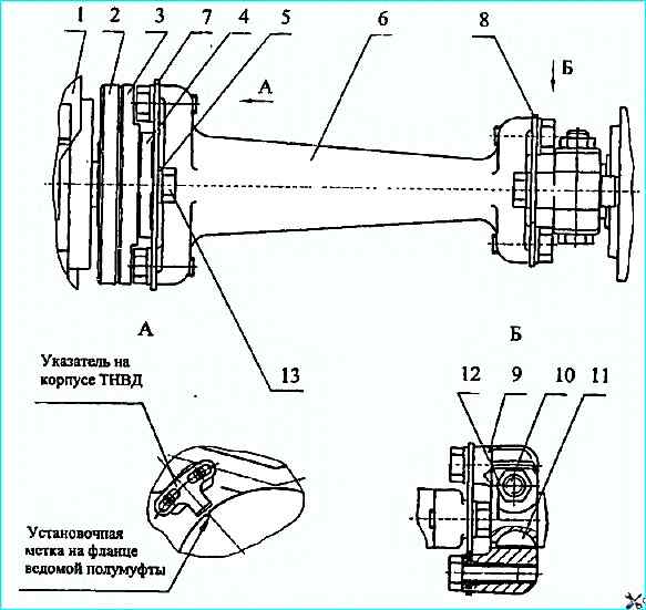
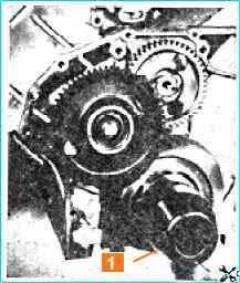
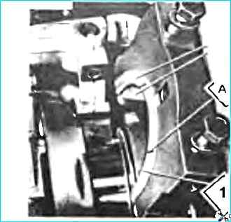
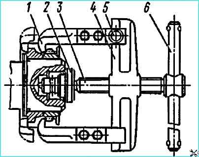
- - loosen the tightening bolt 10 (Fig. 1)
- - remove the rear bearing housing complete with the cuff;
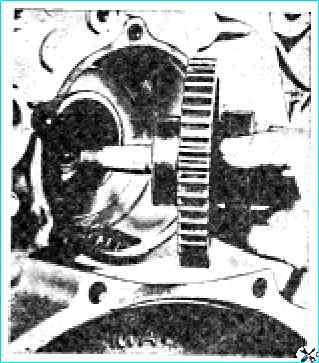
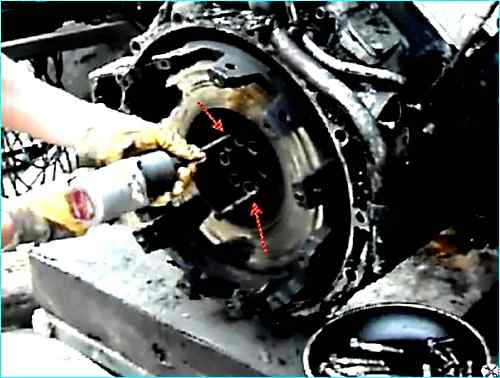
- remove the high-pressure fuel pump drive gear assembly with the shaft (Fig. Removing the high-pressure fuel pump drive gear in assembled with the shaft).
When assembling, align the marks on the ends of the drive gear and the camshaft gear.
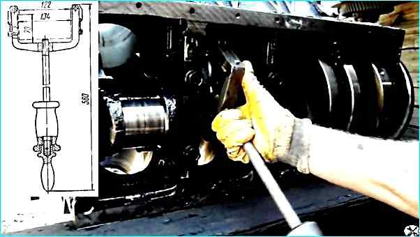
To remove the cylinder liner with puller 801.05.000 (Fig. Removing the cylinder liner with a puller), fold the grip along screw 1 and insert it into the liner in this position.
Having hooked the grip on the lower end of the sleeve 5, set it perpendicular to the screw, then install the supports 4 in the hole on the mating plane of the block and, turning the handle 2, unscrew the screw until the sleeve is completely removed.
To remove the flywheel housing:
- - remove the compressor;
- - remove the power steering pump;
- - unscrew the three bolts and remove the rear eye;
- - remove the brackets securing the fuel drain pipe from the injectors;
- - unscrew the oil dipstick mounting bolt; unscrew the flywheel mounting bolts and the mounting bolts with M8 threads
- - remove the flywheel;
- - unscrew the flywheel housing mounting bolts, remove the housing.
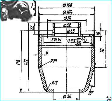
When installing the flywheel housing, use a mandrel (Fig. Mandrel for installing the cuff for the flywheel housing):
- while doing this, generously lubricate the cuff with engine oil.
There are seven repair sizes of liners for repairing the crankshaft, block and connecting rod. The designation of the liners is applied on its back side.
For removing and disassembling the connecting rod-piston group:
- - remove the cylinder head (see "Gas distribution mechanism");
- - remove carbon deposits from the upper belt of the sleeve;
- - remove the lower connecting rod head cover with a puller (Fig. Removing the lower connecting rod head cover with a puller):
- - remove the piston assembly with the connecting rod from cylinder;
- - remove the piston rings with a device (Fig. Removing piston rings with a puller);
- - remove the retaining rings from the piston bosses with pliers И801.23.000;
- - heat the piston in an oil bath to a temperature of 80-100 ° C;
- - remove the piston pin.
When assembling and installing the connecting rod and piston group:
- - install the compression rings with the conical surface (with the UPPER stamp) to the piston bottom, on engines 740.13-260 and 740.14-300, the upper ring is installed so that the inner recess is located on the side bottoms;
- - install the oil scraper rings as follows: first, place the spring expander in the groove, then put on the oil scraper ring so that the expander joint is diametrically opposite the ring lock;
- direct the adjacent rings with the locks in opposite directions;
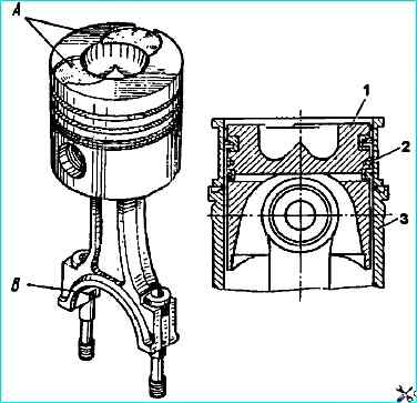
- - when assembling, install the piston and connecting rod so that the recesses A for the valves in the piston crown and the groove "B" in the connecting rod for the locking lug of the liner are on the same side (see Fig. Installing the piston with the connecting rod and rings in the cylinder liner):
- - do not press the pin into the cold piston;
- - when installing the piston in the cylinder, first insert it into the cage I801.00.01 (see Fig. Installing the piston with the connecting rod and rings in the cylinder liner):
- - the index stamped on the piston crown must be the same as the index stamped on the end of the liner, if the piston has not been replaced. Move the recesses for the valves on the piston bottom towards the cylinder block collapse.
The pairing marks from the numbers on the connecting rod and connecting rod cover must be the same.
To remove the crankshaft, dismantle:
- - connecting rod and piston group;
- - flywheel housing;
- - front block cover with fluid coupling assembly;
- - oil pump with oil intake assembly;
- - main bearing caps;
- - remove the crankshaft with a hoist or hoists, hooking brass hooks onto the first and fourth connecting rod journals.
When installing the crankshaft on engine:
- - align the marks on the drive gears of the units;
- - ensure that the sizes of the liners correspond to the sizes of the shaft journals;
- - install the thrust bearing half rings so that the sides with the grooves are adjacent to the thrust ends of the shaft (see Fig. Installing the crankshaft thrust bearing half rings):
- - make sure that the main bearing cap numbers match the serial numbers of the bearings on the cylinder block (see Fig. fig. Installing the main bearing caps) - the numbers start from the front end;
- - tighten the main bearing cap bolts and the block tie bolts in the following sequence:
Clean the threads in the block holes and on the bolts from dirt, lubricate the threads on the bolts with engine oil, remove excess oil.
Install the main bearing caps tightly on the mounting surfaces, without skewing them.
Screw in the M 16 cap mounting bolts with 16x3 washers, ensuring a preliminary tightening torque of 95-120 Nm (9.6 - 12 kgf.m).
Tighten the window carefully tighten the cover mounting bolts, providing a tightening torque of 275-295 Nm (28 - 30 kgf.m)
Insert and tighten the block tie bolts, providing a tightening torque of 147-167 Nm (15-17 kgf.m).
When tightening the bolts with a torque wrench, the resistance should increase smoothly, without jerks. Count the torque while moving the key.
After tightening, the crankshaft should rotate freely from the force of the hand applied to the flywheel mounting pins, the axial clearance in the thrust bearing should be at least 0.05 mm.
Note: During the transition period of production development, the engine may use a cylinder block with screw-on tappet guides, with increased camshaft bushings, without enlarged oil channels, with tightening torques for the main bearing cap bolts:
- - preliminary tightening - 95-120 Nm (9.6-12 kgf.m);
- - final tightening - 206-230 Nm (21-23.5 kgf.m).
- - tie bolts are tightened to a torque of 81-91 Nm (8.2-9.2 kgf m).
For disassembling and assembling the crankshaft:
- - remove the front and rear counterweights, as well as the crankshaft drive gear and the oil pump drive gear using the И801.01.000 puller.
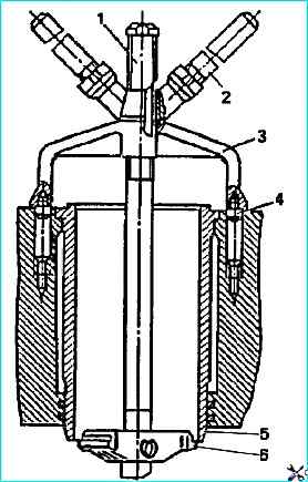
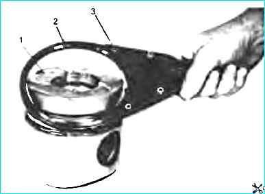
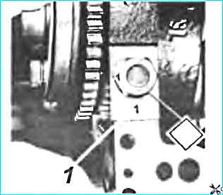
To remove the crankshaft gear and rear counterweight, grip the jaws of the grippers 1 (see Fig. Removing the gear and rear counterweight of the crankshaft with a puller) over the edge of the counterweight gear and secure with stoppers 5.
Put screw 3 through tip 2 against the end of the crankshaft and, turning handle 6, screw screw 3 into crossmember 4 until the gear is completely removed.
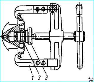
To remove the oil pump drive gear and the front counterweight of the crankshaft (Fig. Removing the oil pump drive gear and the rear counterweight of the crankshaft), install tip 2 on tip 3 and remove the gear in the same way as removing the crankshaft gear;
- - unscrew the insert;
- - clean the oil supply holes from deposits before assembly;
- - wash the shaft and blow out the channels with compressed air;
Note: when using a new crankshaft, it is necessary to unscrew the insert, wash the shaft, blow out the channels with compressed air.
Assemble the crankshaft in the reverse order, before pressing the front counterweight onto the crankshaft, Heat the oil pump drive gear, rear counterweight and crankshaft drive gear to 105 °C.
Dimensions of parts, mm
Piston rings:
- Gap in the compression piston ring lock * 0.4-0.6
- Gap in the oil scraper piston ring lock * 0.30-0.60
- End clearance of the upper compression ring 0.12-0.17
- End clearance of the lower compression ring*. 0.09-0.14
- Oil scraper ring end clearance* 0.077-0.112
Piston:
- Diameter of pin holes. 44.987 - 44.994
- Piston - sleeve joint clearance (at a piston length of 104 mm from the bottom) 0.119-0.162
- * Measure the piston ring clearance in a 0 (120+0.03) mm gauge
Sleeve:
Inner diameter 120.0 0 - 120.021
Piston pin:
- Piston pin diameter 44.993-45.000
- Piston pin - connecting rod upper head joint clearance 0.017-0.031
Bushings:
- Main bearing bushing thickness 2.440-2.452
- Connecting rod journal bearing bushing thickness. 2.453-2.465
Crankshaft;
- Main journal diameter 94.989-95.011
- Main journal bearing clearance 0.085-0.152
- Connecting rod journal diameter 79.9905-80.0095
- Connecting rod journal bearing clearance 0.06-0.104
- Axial clearance 0.100-0.195
- Neck diameter of shaft for front counterweight and oil pump drive gear: 125.080-125.110
- Neck diameter of shaft for Rear counterweight and rear crankshaft gear: 105.070-105.096
- Diameter of the journal of the shaft under the rear cuff: 104.86-105.00
- Diameter of the seat for the bearing of the primary shaft of the gearbox: 51.977-52.008
- Diameter of the hole for the flywheel mounting sleeve: 51.977-52.008
Half rings of the thrust bearing of the fifth main bearing of the crankshaft
Thickness 4.010-4.050
Cambral shaft
- Diameter of the intermediate bearing journals 59.895 - 59.915
- Diameter of the sleeve of the intermediate bearing journals 60.00 - 60.03
- Diameter of rear bearing journal. 41.930 - 41.950
- Diameter of rear bearing journal bushing. 42.000 -42.015
- Gap in the connection of bushing - intermediate bearing journals of the camshaft: 0.135 -0.085
- Gap in the connection of bushing - rear bearing journal of the camshaft: 0.085 - 0.050
- Gap in the connection of the end face of the rear bearing housing - gear hub: 0.15-0.30
Timing belt parts
Pusher rod diameter. 21.993 -21.972
Pusher guide hole diameter 22.000 - 22.023
Gap between pusher rods and guide: nominal 0.007 - 0.051
Gap between valve rod and guide, mm:
- - intake 0.03 - 0.072
- - exhaust 0.07-0.112
Angle α of seat chamfer (intake, exhaust) 45° - 45°15
Angle γ of valve chamfer (intake, exhaust) 44°45 - 45°
For removing the cylinder head during replacement, as well as for troubleshooting valve mechanism and cylinder-piston group faults:
- - drain the coolant from the engine cooling system;
- - unscrew the exhaust manifold mounting bolts and remove the manifold;
- - unscrew the intake air duct and water collection pipe mounting bolts from the head being removed, loosen the fastenings of these same bolts
On other heads, in order to obtain the necessary clearance for removal;
To remove the right-hand cylinder heads, first remove the compressor from the engine.
- - remove the connecting pipe of the intake air ducts;
- - disconnect all pipelines from the head and protect their cavities from dust and dirt;
- - remove the nozzle, protecting the sprayer from impacts and clogging of the holes, the cylinder head cover, racks together with rocker arms and rods;
- - loosen the cylinder head mounting bolts, observing the same sequence as when tightening (Fig. Sequence of tightening the cylinder head bolts), then unscrew them;
- - remove the cylinder head from the engine.
When installing the cylinder head, pay attention to the correct installation of the gaskets.
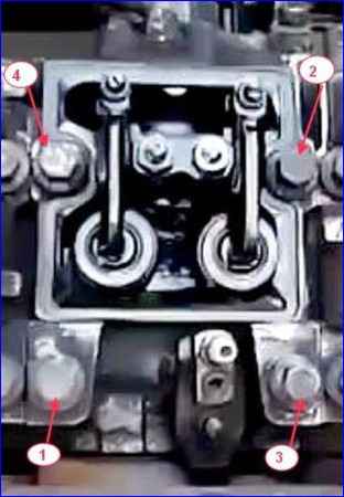
Tighten the cylinder head bolts in three stages in the sequence shown in Fig. Sequence of tightening the cylinder head bolts.
After tightening the bolts, check and, if necessary, adjust the thermal clearances between the valves and rocker arms.
For disassembling and assembling the valve mechanism using the И801.06.000 device (see Fig. Disassembling the cylinder head using the И801.06.000 device):
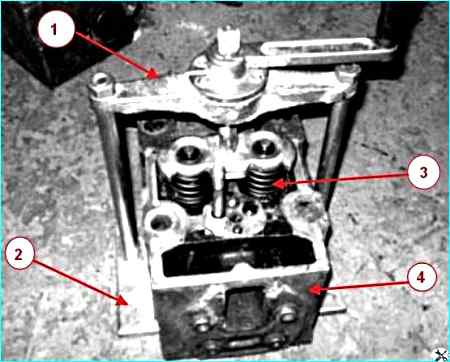
- - install the cylinder head on the base so that the pins enter the pin holes of the head;
- - turn the handle, screw in the screw and press the valve springs with a plate;
- - remove the crackers and bushings;
- - unscrew the screw from the crossmember, remove the plate and valve springs;
- - take out the intake and exhaust valves.
When assembling the valve mechanism, lubricate the valve stems with diesel oil.
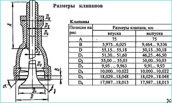
Valve dimensions are given in the figure
To grind the valves:
- - disassemble the valve mechanism as described above;
- - prepare a paste of 1.5 parts (by volume) of green silicon carbide micropowder, one part of diesel oil and 0.5 parts of diesel fuel. Mix the grinding paste before use those (micropowder can settle);
- - apply a thin, even layer of paste to the chamfer of the valve seat, lubricate the valve stem with engine oil. Lapping is performed by reciprocating and rotating the valve with a drill with a suction cup or device.
Pressing the valve, turn it 1/3 of a turn, then 1/4 of a turn in the opposite direction. Do not grind the valves using circular motions.
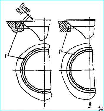
Continue grinding until a uniform matte belt at least 1.5 mm wide appears on the valve and seat chamfers (Fig. Location of the matte belt on the valve seat);
- after grinding, wash the valves and cylinder head with diesel fuel and blow with air.
Assemble the valve mechanism as described above and determine the quality of the valve grinding by checking for leaks:
- install the cylinder head alternately with the inlet and outlet ports up and fill them with diesel fuel. Well-ground valves should not leak it at the sealing points for 30 seconds.
If fuel leaks, tap the end of the valve with a rubber hammer. If the leakage does not stop, grind the valves again.
If necessary, check the quality of the grinding "with a pencil" by applying six to eight lines at equal distances across the valve chamfer with a soft graphite pencil.
Carefully insert the valve into the seat and, pressing hard, turn it ¼ turn, all the lines should be erased, otherwise, grind again.
When grinding correctly, the matte belt on the head seat should begin at the larger base of the seat cone, as shown in the figure
")

")
")
")
")
")
")
")