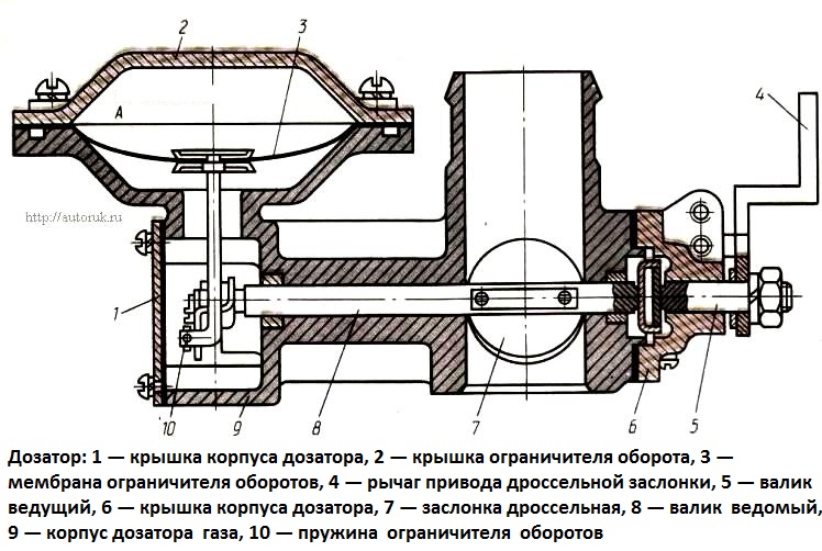
The dispenser is mounted on the mixer body and is designed to regulate the supply of the required amount of gas to the mixer in various engine operating modes
The dosing device is made in the form of a throttle valve 7 installed on the inlet channel of the housing 9 and fixed on the roller 8.
The damper is controlled by the accelerator pedal from the cab through a system of rods, levers and roller 5.
When the damper is opened to a greater angle, the flow of gas passing through the mixer diffuser increases.
When the damper closes, the gas supply stops.

When the maximum idle speed of the engine operating in gas-diesel mode is reached, the pilot dose of liquid fuel is turned off.
To turn off the gas supply at this moment, a vacuum restrictor is used, combined with a dispenser in one housing.
The limiter allows you to control the position of the throttle valve regardless of the position of the lever 4 of the damper drive, for example, turn it towards closing when the engine reaches the maximum allowable speed (2550 rpm).
The vacuum limiter works in conjunction with a three-way solenoid valve and an inductive engine speed sensor.
If the engine speed does not exceed the permissible value, the solenoid valve communicates cavity A with the atmosphere.
In this case, the membrane bends down under the action of spring 10 and the membrane rod does not prevent the roller 8 from turning in the direction of opening the damper with lever 4.
When the maximum permissible crankshaft speed is exceeded, the induction sensor activates the solenoid valve through the electronic control unit.
At the same time, the valve separates cavity A from the atmosphere and imparts to it the rarefaction of the diffuser.
As a result, the membrane 3 bends upward and covers the throttle valve 7 through the rod and shaft 8, overcoming the force of the spring 10. The flow of gas into the mixer stops.


