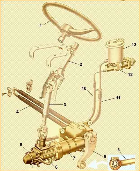
The steering consists of a steering wheel 1, a column 2, the shaft of which is connected through a cardan transmission 3 to the steering mechanism 7, and a steering gear.
The steering gear is a system of rods and levers that, together with the steering mechanism, turns the car.
Through the steering mechanism, the longitudinal rod 8 moves forward or backward, thereby causing one wheel to turn left or right, and the steering linkage transmits the turning moment to the other wheel.
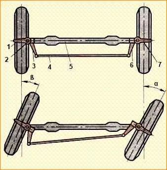
The trapezoid includes beam 5 (Fig. 2.) of the front axle, levers 3 and 6 of the steering knuckles and tie rod 4.
When one wheel turns through levers 3 and 6 and rod 4, the other wheel also turns.
In this case, due to a change in the position of the transverse link 4 relative to the front axle, the inner wheel towards the center of rotation turns at an angle greater than the angle of rotation of the outer wheel.
The steering mechanism of KamAZ vehicles includes an angular gear reducer, a screw-nut transmission with circulating balls and a rack-gear pair.
The steering gear housing is also the power steering housing, with which the steering gear is integrated.
The gear ratio of the angular gearbox is 1:1, the steering gear of cars with a 6X4-20 wheel arrangement: 1, off-road vehicles - 21.7:1.
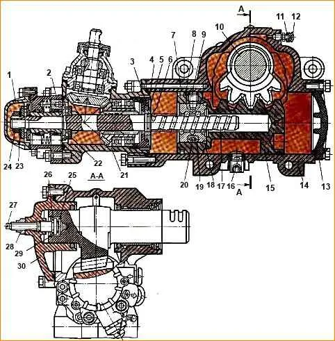
The steering mechanism consists of a housing 14 (Fig. 3.), in which a piston-rack 15 moves, which engages with the toothed sector of the bipod shaft 10.
The ball nut 18 is secured in the piston-rack with set screws 9.
The screws are locked by opening them in the groove of the piston-rack.
Ball nut 18 and screw 17 have helical grooves.
On the outer surface of the ball nut there is an oblique groove connected by two holes to its helical groove.
Two grooves 19 are inserted into this groove, forming together a tube, which is like a continuation of the helical groove.
The screw channel formed by the grooves of the screw and nut and grooves contains 20 balls.
As the screw rotates, the balls roll out from one side of the nut, pass through the grooves, as if through a bypass channel, and return to the screw channel, but on the other side of the nut.
A total of 31 balls circulate in the closed channel, 8 of which are in the bypass channel.
The thickness of the teeth of the bipod shaft sector and the piston-rack is variable along the length, which allows you to change the engagement gap by axial movement of the adjusting screw 27 screwed into the side cover 30.
The free axial movement of the bipod shaft after assembling the steering mechanism should be 0.02-0.08 mm, which is ensured by changing the thickness of the adjusting washer 26.
On the part of the steering gear screw located in the cavity of the angular gear housing 21, there are splines with which the screw is connected to the angular gear gear.
Removal and repair of the steering mechanism
To remove the steering gear:
- - Move the cabin to the first position (42°);
- - having unscrewed and unscrewed the nuts, remove the bipod coupling bolts 9 (see Fig. 1) or, bending the antennae of the lock washer, unscrew the nut of the upper head of the bipod;
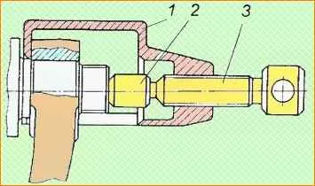
- - use a puller to remove the bipod, screwing screw 3 (Fig. 4) into the grip 1 of the puller and resting the tip 2 against the end of the bipod shaft (knocking out the bipod can cause breakage of parts);
- - unscrew the magnetic plug and drain the oil from the steering gear housing; for more complete drainage, turn the steering wheel two or three times from one extreme position to the other;
- - disconnect the high and low pressure pipelines from the steering mechanism and drain the remaining oil in the pump;
- - disconnect the steering driveshaft from the steering mechanism, to do this, remove the cotter pin, unscrew the wedge nut and knock out the wedge;
- - unscrew the bolts securing the steering gear housing to the front spring bracket and remove the steering gear;
- - clean and rinse the outer surface of the steering mechanism;
- - drain the remaining oil by turning the steering mechanism with the valve down and turning the shaft of the bevel gear drive gear two or three times from one extreme position to the other.
- When installing the steering gear on a vehicle:
- - install the mechanism on the front bracket of the left front spring and secure it with bolts with a tightening torque of 275-314 Nm (28-32 kgf);
- - connect the discharge and drain pipelines to the power steering control valve;
- - attach the steering cardan shaft to the steering mechanism, having previously aligned the hole in the cardan fork and the wedge flat on the drive gear shaft, hammer in the wedge, tighten and pin the nut with a tightening torque of the wedge nut of 13.7-16.7 Nm( 1.4-1.7 kgcm);
- - fill in oil and bleed the power steering system (see section “To change the oil”);
- - having previously opened the slot of the upper head of the bipod with a wedge, put the steering bipod on the steering gear shaft, insert the coupling bolts, screw the nuts onto the bolts, tighten them and pin them with a tightening torque of 177-196 Nm (18-20 kgcm). The bolt nuts should be located on opposite sides of the bipod head;
- - check the tightness of the connections and hoses of the steering hydraulic system. Do not allow oil to leak from the connections.
Disassemble and check the steering mechanism in the following order:
- After unscrewing the fastening bolts, remove the side cover along with the bipod shaft. When removing the bipod shaft, first clean its splined end.
- Check the axial movement of the adjusting screw in the bipod shaft. If the movement exceeds 0.15 mm, adjust the axial clearance by selecting a shim. The adjusting screw must have an axial movement relative to the bipod shaft of 0.02-0.08 mm and rotate smoothly, without jamming. The retaining ring must fit completely into the groove of the bipod shaft. This is necessary for reliable connection of the parts of this assembly. If necessary, replace the adjusting screw O-ring using a mandrel. After assembling the side cover, the bipod shaft should rotate freely by hand, and the adjusting screw should remain motionless (check without the locknut).
- After unscrewing the mounting bolts, remove the front cover. During all subsequent disassembly and assembly operations, remember that turning the steering gear screw out of the ball nut more than two turns from the middle position may cause
- Unscrew the nuts securing the power steering control valve housing and carefully push the housing forward enough so that it can be rotated relative to the screw without touching the bevel gear housing studs.
- Check that the thrust bearing nut is tight and that the control valve body rotates smoothly relative to the screw.
The torque required to rotate the control valve body must be equal to 98.1-122.6 N cm (10-12.5 kgf cm) (during operation, the rotation torque is allowed to drop to 34.3 N cm (3. 5 kgf cm). If the torque does not correspond to the specified value, adjust the tightening of the thrust bearing nut. If the rotation of the valve body is not smooth (rotation resistance is variable), replace the bearings. To adjust the tightening or replace the bearings, it is necessary to press the nut collar pressed into the screw groove and unscrew the nut , holding the drive gear of the angular gearbox from turning.
Warning: When unscrewing the thrust bearing nut, be sure to hold the drive shaft of the angular gearbox from turning. Failure to comply with this rule leads to breakage of the tendril of spring washer 23 (see Fig. 3) and damage to the threads of screw 17. When removing the control valve body, make sure that the spool and reaction plungers do not fall out, since during factory assembly each of them is individually matched to its hole. Do not mix thrust bearing rings, keep them complete.
- Check smoothness with your hand movements of the reaction plungers and spool in the body of the power steering control valve. If you feel any jamming or a change in the force required to move the mentioned parts, remove the jammed parts one by one. Eliminate the cause of the jamming, wash and replace them.
- Check the tightness of the check valve by pouring oil into its hole. Oil leakage is only permissible in the form of individual drops.
- After unscrewing the mounting bolts and two nuts, remove the bevel gear along with the screw and piston-rack.
- Use pliers to remove retaining ring 3 (see Fig. 3) and carefully remove the bevel gear from the screw.
- Check for axial movement of the ball nut relative to the piston-rack. If necessary, tighten or replace the two set screws and unscrew them. 11. Check the fit of the ball nut on the middle part of the helical groove of the screw. The nut should rotate on the screw without jamming, and its axial play relative to the screw should not exceed 0.3 mm. If the rotation of the screw in the ball nut is not smooth, provided that the axial play does not exceed 0.3 mm, replace the set of balls.
To replace a set of balls, first do the following:
- - use a special wrench with a sufficiently large shoulder to unscrew the set screws of the ball nut;
- - remove the ball nut and screw from the piston-rack, holding the grooves and balls from falling out;
- - remove the grooves, inspect them and, if the tongues are damaged, replace them;
- - then, turning the screw relative to the nut in one direction or another, remove the balls and put them in a separate box. Installation of balls with a diameter difference of more than 0.002 mm is not allowed. Failure to comply with this requirement may result in destruction of the balls and jamming of the steering mechanism. After replacing the balls, the nut should rotate in the middle part of the screw thread under the influence of a torque of 29.4-78.5 Nm (3-8 kgcm), the nut should fit freely at the edges. The raceways on the screw and nut must not be damaged. If the raceways are damaged (dented, burred, etc.), replace the entire screw-ball nut-ball assembly.
- Inspect the working surfaces of the hydraulic booster. If there are individual burrs on the cylinder mirror, remove them with a scraper. Individual longitudinal marks and scratches on the cylinder mirror (without burrs) are not a defective sign.
- Check the adjustment of the side clearance between the teeth of the bevel gears. The lateral clearance between any pairs of teeth should be in the range of 0.02 - 0.07 mm, and the rotational moment of the drive gear in the bevel gear should not exceed 49.1 N.cm (5 kgf.cm).
Adjustment of the lateral clearance in the teeth of the gearbox gears is carried out by moving the drive gear assembly by selecting a pack of gaskets under the flange of the drive gear housing. In this case, at least three gaskets with a thickness of 0.05 mm must be installed.
When the bevel gears mesh correctly, the contact pattern should be elliptical and located closer to the inner narrow part of the tooth. It is unacceptable for the contact patch to reach the edges of the tooth. When disassembling the bevel gear, do not disturb the complete set of the bevel gear housing and the pair of bevel gears.
Assemble the steering mechanism in a clean environment in the reverse order of disassembly, in accordance with the following instructions:
- Rinse and dry all parts of the disassembled mechanism, blow out the internal channels and holes after washing with dry compressed air. Do not wipe parts with a rag, which may leave threads, lint, etc.
- Before assembly, lubricate all contacting surfaces of the steering mechanism parts with Turbine oil Tn-22 GOST 9972-74 or oil grade R.
- Inspect and replace all rubber sealing parts. The fluoroplastic rings of the piston and screw seals must not be damaged. To facilitate the installation of rubber rings and to avoid pinching them during assembly, it is allowed to use PVK lubricant GOST 19537-74.
- In case of replacing the cuffs of the bipod shaft and the drive gear shaft of the bevel gear, press them in smoothly and without distortions, using mandrels. Finally, press the specified cuffs in a package together with the outer cuff and other parts included in the mentioned seal assembly units - until they stop in the mechanism body. When installing the bipod shaft cuffs, their working edges must be protected from damage by the shaft splines.
- The tightening torque of M8 bolts should be 20.6-27.5 Nm (2.1-2.8 kgcm), M10 bolts and nuts - 34.3-41.2 Nm (3.5-4.2 kgcm). The thrust cover of the driven gear assembly unit of the gearbox must be tightened with a torque of 43.2-60.8 Nm (4.4-6.2 kgcm) and locked by opening its edge into the groove on the bevel gear housing.
The nut securing the bearings of the bevel gear drive gear must be tightened to a torque of 39.2-58, 9 Nm (4-6 kgcm) and is locked by pressing the collar of the nut into the groove on the drive gear shaft. After assembly, the driven and driving gears of the angular gearbox should rotate freely and have no noticeable axial play. Tighten the magnetic drain plug (with a tapered thread and a cylindrical magnet) to a torque of 33.4-39.2 Nm (3-4 kgcm).
- Assemble the ball screw pair and install the assembled set into the piston-rack in the following order:
- - place a floating sealing sleeve on the screw from the side of its screw groove;
- - install the nut on the lower end of the screw, aligning the holes of the nut into which the grooves fit with the screw groove of the screw;
- - place twenty-three balls through the hole in the nut facing the bevel gear, turning the screw counterclockwise;
- - place eight balls in the grooves folded together and prevent them from falling out by covering the outlets of the gutter with PVK grease GOST 19537-74;
- - insert the grooves with the balls into the nut, turning the screw if necessary, and tie the nut to prevent the grooves from falling out;
- - check the torque of the nut on the middle part of the screw (should be equal to 29.4-78.5 N.cm (3-8 kgf.cm); if the torque does not correspond to the specified value, replace the set of balls, avoiding mixing the sets;
- - press the nut with the screw into the hole of the piston-rack, screwing in and opening the set screws in two places against the grooves in the piston-rack. The tightening torque of the set screws should be 49.1-58.9 Nm (5-6 kgcm). If the groove in the piston-rack coincides with the screw slot, replace the latter. Protrusion of the screws above the cylindrical surface of the piston-rack is unacceptable. This will cause scuffing of the working surface of the power steering cylinder.
- When assembling an angular gearbox with a screw and a floating sealing sleeve, make sure that the retaining ring of the latter is securely installed in the groove of the thrust cover of the angular gearbox. The retaining ring must fit completely into the said groove.
- Install the piston-rack into the crankcase using a mandrel without distortion.
- When assembling the power steering control valve, make sure that the groove on the end of the spool faces the bevel gear, and the chamfers on the reaction plungers face outward. After assembly, the spool, check valve, and reaction plungers should move smoothly in the corresponding holes of the control valve body, without jamming.
- When assembling the power steering control valve with a screw, install the thrust bearings so that their large rings face the spool. The spring washer of thrust bearings must be installed with the concave surface towards the bearing. After adjusting the torque required to rotate the control valve body (98.1-122.6 N.cm (10-12.5 kgf.cm), lock the thrust bearing mounting nut by pressing the nut collar into the groove of the steering gear screw.
- When assembling the adjusting screw and the bipod shaft, ensure that the axial movement of the screw relative to the bipod shaft is 0.02-0.08 mm by selecting an adjusting washer. If necessary, replace the adjusting screw O-ring using a mandrel.
- Adjust the gearing in the pair “piston - rack - gear sector of the bipod shaft” in accordance with the instructions stated above. After adjusting the engagement, tighten the adjusting screw of the bipod by tightening the lock nut with a torque of 58.9-63.8 Nm (6-6.5 kgcm), while holding the adjusting screw from turning.
After assembly, the steering mechanism must meet the following requirements:
- The full angle of rotation of the bipod shaft must be at least 90°.
- After rotating the steering gear screw until the piston stops and applying an additional torque of at least 19.6 Nm (2 kgcm) to the drive gear, the centering springs should ensure its clear return to its original position. This condition must be observed when turning both right and left.
- The torque applied when rotating the drive gear (or the force on the steering wheel rim applied over a radius of 250 mm) must be:
- - after turning the drive gear more than two turns in any direction from the middle position - 147-294 N.cm (15-30 kgf.cm [the force on the steering wheel rim is 5.9-11.8 N (0 ,6-1.2 kgf)];
- - when turning the drive gear with a transition through the middle position with a guaranteed gap in the gearing of the rack-piston and the bipod shaft - 196-441 N.cm (20-45 kgf.cm) [the force on the steering wheel rim is 7.8 -17.7 N (0.8-1.8 kgf)];
- - when turning the drive gear with a transition through the middle position after adjusting the gearing of the rack-piston and bipod shaft - 98.1-147.2 Nm (10-15 kgf.cm) [by 3.9-5.9 N (0 ,4-0.6 kgf) more than with a guaranteed gap], but not more than 540 N.cm. (55 kgf.cm) [21.6 N (2.2 kgf)].
- Additionally test the steering mechanism on a stand equipped with a pump with a flow rate of at least 9 1/min and providing oil supply to the hole in the power steering control valve housing. Conduct the test on grade P oil at a temperature not lower than plus 40°C. Before testing, remove air from the system.
Adjust the safety valve of the bench pump to an opening pressure of 5390 kPa (55 kgf/cm 2) and check:
- - rotation of the drive gear in any direction at a moment of resistance to rotation of the bipod shaft of 0 and 1275 Nm (130 kgcm) should be smooth, without jamming;
- - the pressure at the inlet to the hydraulic booster control valve with the spool in the neutral position should be no more than 294 kPa (3 kgf/cm 2);
- - moment on the drive gear with a resistance on the bipod shaft of 1275 Nm (130 kgf.cm) - no more than 1766 N.cm (180 kgf.cm);
- - leakage at the outlet of the power steering control valve when turning the drive gear all the way to the right or left (measuring time no more than 20 s, measurement starts 5 s after turning the screw all the way) - no more than 1200 cm 3/min;
- - rotation of the bipod shaft from one extreme position to another should occur from a force with a moment of no more than 118 Nm (12 kgcm). Adjust the bench pump safety valve to an opening pressure of 90 rpm and check:
- - pressure in the discharge line when the drive gear is turned all the way to the right and left; it should be 7355-7846 kPa (75-80 kgf/cm 2). After removing the force from the screw without braking and stopping the drive gear shaft, the pressure should quickly drop to a value of no more than 294 kPa (3 kgf/cm 2);
- - tightness of the steering mechanism in both extreme positions of the piston (5 min in each position) at a pressure of 8826 kPa (90 kgf/cm 2). Ensure pressure by installing a valve on the return line;
- - correctness of switching characteristics. The free play on the drive gear shaft (the angle of rotation of the shaft until the pressure in the pressure line increases by 78.5 kPa (0.8 kgf/cm 2) should be 3-5° in each direction. The total free play movement (sum of angles to the right and left) is allowed no more than 10°.
")

")
")
")
")
")
")
")