The starter is a sealed series-excited DC electric motor with an electromagnetic traction relay and a drive with a freewheel ratchet mechanism
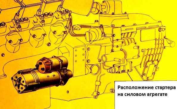
Starter activation is remote.
The drive gear is forced into engagement with the flywheel ring using an electromagnetic traction relay.
The starter is designed to operate in a single-wire circuit, where the second wire is engine ground.
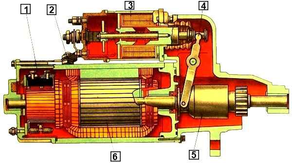
KamAZ engines are equipped with an ST142B starter (Fig. 1), the rated voltage of which is 24 V, the rated power is 7.7 kW, the no-load current at a voltage of 24 V should be no more than 130 A.
The engine-starter gear ratio is 11.3.
The cover contains four poles of excitation windings made of rectangular copper wire.
The windings are connected in parallel-series, c. In this case, the resistance of four coils (at four poles) is equal to the resistance of one coil.
The brush holders are mounted on a traverse, which is attached to the cover with four bolts.
Each brush holder contains two brushes, pressed to the commutator by springs.
The armature rotates in three sliding bearings, the bearings of which are lubricated with turbine oil 22 (motor oil can be used).
The starter covers and the intermediate support have oil reservoirs with folds that are hermetically sealed.
The starter is sealed using O-rings with a circular cross-section.
The output bolts of the starter and traction relay are sealed with rubber washers, and the traction relay armature is protected by a rubber bellows.
The starter shaft at the intermediate support on the drive side is protected by a reinforced rubber cuff.
The cover on the collector side is made without inspection windows.
When disassembling and assembling the starter, it is necessary to carefully monitor the condition of the gaskets and their contact areas so as not to break the seal of the starter.
The starter traction relay is installed on its body; when the armature moves, the contacts of the traction relay are closed by a disk disk and the drive clutch gear is forced into engagement with the flywheel ring.
The drive mechanism moves along the straight splines of the armature shaft.
The traction relay has contacts and two windings: retracting and holding.
The windings are wound on a brass bushing, with the retractor being wound first and then the retaining one.
The resistance of the holding winding is greater than the resistance of the retracting winding. The beginnings of both windings are connected to a terminal attached to a plastic cover.
The end of the retractor winding is connected to the output bolt, and the end of the retaining winding is connected to the housing.
The armature stroke of the traction relay when the starter is turned on is about 20 mm.
With such an air gap, a large magnetic flux is required to move the armature (the attractive force is proportional to the square of the magnetic flux).
Therefore, at the moment the starter is turned on, the magnetic flux is created simultaneously by the retractor and holding windings, and as soon as at the end of the movement of the traction relay armature its contacts close and the starter turns on, the magnetic flux of the retractor winding (current in the winding) will disappear, since the contacts of the traction relay when deputies The cables bypass the power supply circuit and the pull-in winding.
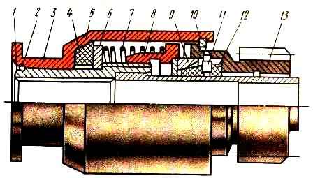
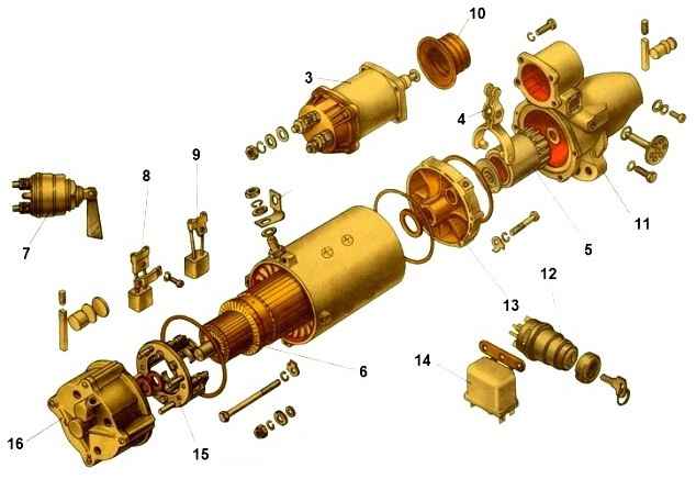
The starter uses a ratchet drive mechanism shown in the figure
The drive parts are located on the guide sleeve 1, which has straight internal splines and a multi-start external tape thread.
The bushing, together with the drive, can move along the splines of the starter shaft. The drive coupling half 8 is located on the external thread of bushing 1.
The driven coupling half 13 is made integral with the gear and can rotate freely on the sleeve 1 in bronze graphitized bearings.
The ends of the coupling halves are equipped with teeth and are pressed against one another by a spring 7.
The driven coupling half 13 is locked in the housing 5 by a locking ring 10. The locking ring 2 keeps the housing 5 from moving on the sleeve 1.
To absorb shocks when the starter is turned on, a steel washer 6 and a rubber ring 4 are placed under the spring 7.
To prevent wear of the teeth of the ratchet clutch and reduce noise when the engine is started and the starter is not yet turned off, a locking mechanism is provided.
Inside the driven coupling half 13 there are three plastic cotters 12 with radial holes into which guide pins 11 fit.
The outer surface of the crackers has a conical chamfer adjacent to the groove of the steel ring 9 installed in the drive coupling half 8. Ring 9 presses the crackers 12 to the guide sleeve 1.
When torque is transmitted to the engine flywheel, an axial force occurs, pressing the driving half of the coupling to the driven half.
As soon as the engine is started, the ratchet clutch will slip.
During slipping, the driving coupling half 8 moves away from the driven coupling half 13, compressing the spring 7.
Together with the drive half-clutch 8, ring 9 moves away, releasing the crackers 12, which, under the influence of centrifugal forces, move along the pins 11 and block the clutch in the disengaged state.
After turning off the starter, the driving coupling half 8, under the action of the spring 7, is pressed against the driven coupling half 13 and the ring 9 will set the crackers 12 to their original position.
Replacing ST142B starter
We replace the starter in case of the following malfunctions:
- - short circuit of the armature windings or field windings;
- - damage to the freewheel ratchet drive;
- - burning or contamination of the collector;
- - open circuit of the starter or traction relay;
- - anchor jamming (the anchor does not turn or turns with great effort);
- - destruction or wear of gear teeth
Removing the starter
Turn off the vehicle weight and raise the cab to the first position
Disconnect the red wire and the white wire from the “+” terminal, and the black wire from the traction relay terminal
Disconnect the ground wire (black) from the starter by unscrewing the bolt on the starter housing
Unscrew the nut and unscrew the three bolts securing the starter to the flywheel housing
Supporting the starter by the body, move it forward and remove the starter (it is advisable to do this with an assistant)
Installing the starter
Install the starter on the flywheel housing, putting it on the pin
Tighten the nut and screw in the three bolts securing the starter to the flywheel housing
Connect the ground wire to the starter by screwing the bolt into the starter housing
Connect the remaining wires
Checking the starter operation
")

")
")
")
")
")
")
")