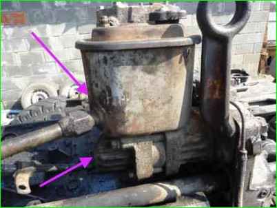
KAMAZ power steering pump
The power steering pump with an oil reservoir is installed in the camber of the cylinder block and is driven by the engine crankshaft
The pump is a vane type, double-action, i.e., for one revolution of the shaft, two complete suction cycles and two discharge cycles are completed.
The position of the stator 37 relative to the housing 40 and the distribution disk 34 is fixed with pins.
An arrow on the outer surface of the stator indicates the direction of rotation of the pump shaft.
When shaft 5 of the pump rotates, the plates are pressed against the curved surface of the stator under the action of centrifugal force and oil pressure entering the space underneath them from the cavity
In the pump cover 29 through the channels in the distribution disk.
Chambers of variable volume are formed between the plates and the end surfaces of the pump housing and the distribution disk.
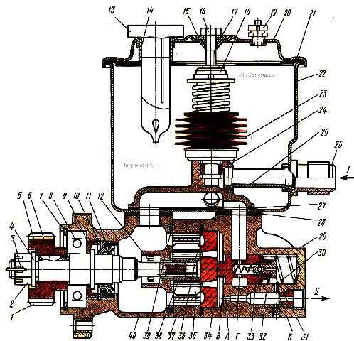
Power steering pump: 1 - drive gear; 2 - gear fastening nut; 3 - cotter pin; 4.15 - washers; 5 - pump shaft; 6 - segment key; 7, 10 - thrust rings; 8 – ball bearing; 9 - oil removal ring; 11 - cuff; 12 - needle bearing; 13 - filler cap; 14 - filler filter; 16 - bolt; 17, 36, 39 - sealing ring; 18 - filter pipe; 19 - safety valve; 20 - tank cover with a spring; 21, 28 - sealing gaskets; 22 - pump reservoir; 23 - filter element; 24 - collector; 25 - tank tube; 26 - fitting; 27 - manifold gasket; 29 – pump cover; 30 - bypass valve spring; 31 - safety valve seat; 32 - adjusting washers; 33 - bypass valve assembled with a safety valve; 34 - distribution disk; 35 - pump plate; 37 - starter; 38 - rotor; 40 - pump housing; A, B - throttling holes; B - injection cavity; G - radial holes; I - from the system; II - into the system
At each moment of time, two of them form a suction zone: the space between the plates is filled with oil, and the other two are discharge zones: the volume between the plates decreases, and the oil is forced out through channels in the distribution disk into the cavity of the pump cover, communicating through a calibrated hole " A" with discharge line.
In the pump cover there is a combination valve 33, which combines a safety valve and a bypass valve.
The safety valve is adjusted to a pressure of 85-90 mPa, and the bypass valve regulates the amount of oil entering the system.
At minimum crankshaft speed, the bypass valve is pressed by spring 30 to the distribution disc.
Oil from the cavity in the pump cover through calibrated hole “A” enters the channel connecting to the discharge line.
The cavity under the valve, where the spring 30 is located, communicates with this channel through a small diameter hole “B”.
With an increase in the crankshaft rotation speed, and hence the oil supply to the pumps, a pressure difference is formed (due to the hydraulic resistance of hole “A”) in the cover cavity (in front of the valve) and in the pump discharge channel (behind the valve).
The pressure difference is greater, the more oil passes per unit time through hole “A”, and does not depend on the pressure value.
Excess pressure in cavity “B”, acting on the left end of the bypass valve, overcomes the resistance of spring 30.
At a certain pressure difference, the force tending to move the valve increases so much that the spring is compressed and the valve, moving to the right, opens the exit of part of the oil from the working cavity “B” of the lid into the tank.
The more oil the pump supplies, the more of it is passed through the valve back into the tank. Thus, as much oil enters the system as required.
At low oil flows and increased pressure in the spring cavity, the built-in safety valve is activated, and the bypass valve will operate similarly.
Opening, the safety valve allows a small flow of oil into the tank through the radial holes "G".
In this case, the pressure on the right end of the bypass valve decreases due to the resistance of channel “B”.
Valve 33 moves to the right and opens the outlet to the tank for the main part of the bypassed oil.
The safety valve should be adjusted using shims 32.
To prevent noise and slow down wear of parts when operating the pump with With a high rotation speed and intensive oil bypass, a manifold 24 is provided, which directs this oil into the internal cavity of the pump housing and provides excess pressure in the suction zones.
In the pump tank 22 there is a collapsible strainer 23, which is a package of individual filter elements, which, in case of significant clogging, is pressed upward by increased pressure in the cavity of the filter tube.
In this case, the oil flows directly into the tank.
In addition, the tank contains a fill filter 14 and a safety valve 19, which prevents air pressure in the tank from exceeding 30 kPa.
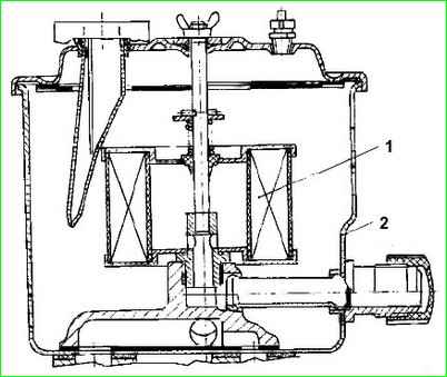
Power steering pump filter: 1 - pump filter; 2 - pump reservoir
For modernized cars
The filter, located in the power steering pump reservoir, is made in the form of a non-separable structure (Fig. 3), consisting of a paper curtain placed between two metal shells, which are glued to the upper and lower filter covers
")

")
")
")
")
")
")
")