Ten-speed Kamaz gearbox
Ten-speed gearbox. It consists of a main five-speed gearbox and a front attached gearbox - a gear divider, due to which it has ten gears for moving forward and two gears for moving backward
The fifth lowest gear is direct, the fifth highest gear is accelerating.
The gear ratios of the box are as follows: IH - 7.82, IB - 6.38; IN—4.03, IIB—3.29; IIIH - 2.5: IIIB - 2.04; IVH - 1.53, IVB - 1.25; VH-1.00, VB - 0.815, ZHN - 7.38, ZHV - 6.02
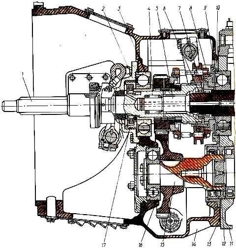
Ten-speed gearbox model 15 (divider assembly with gearbox): 1 - input shaft of the divider; 2 - rear bearing cover; 3 - ball bearing; 4 - front roller bearing of the gearbox input shaft; 5 - gearbox input shaft; 6 - ring nut; 7 - washer; 8 - divider synchronizer; 9 - adjusting shims; 10 - cover of the rear bearing of the input shaft; 11 - gearbox housing; 12 - spacer sleeve; 13 – sealing gasket; 14 - gear divider housing; 15 - intermediate divider shaft; 16 - front bearing of the intermediate shaft of the divider; 17 - oil injection ring
The main gearbox is based on the five-speed gearbox described earlier, and has a similar device to it, with the exception of the following:
- - the gearbox is attached to the housing 14 (Fig. 1), made integral with the clutch housing;
- - oil injection ring 17 is installed on the input shaft 1 of the divider, and not on the input shaft of the gearbox;
- - rear bearing 3 of the input shaft is secured with a special ring cover 2;
- - due to the installation of the intermediate shaft 15 of the divider, the bearing cover of the intermediate shaft of the gearbox is missing;
- - to the input shaft 5 of the gearbox, the torque from the driven clutch discs is transmitted through the divider and therefore there are no splines for installing the driven clutch discs;
- - front bearing 4 of the gearbox input shaft is installed in a special socket of the divider input shaft, and not in the crankshaft bore;
- - to engage the low gear of the divider, splines are cut on the input shaft of the gearbox, on which a gear coupling with a cone pressed onto it is installed to ensure the operation of synchronizer 8.
The end of the cone rests against the inner ring of the bearing, and the coupling is fixed on the shaft with nut 6.