The rear suspension of three-axle cars is balanced on two springs.
With such a suspension, the intermediate and rear axles swing relative to the balancer axis
In this case, the springs perceive only the force of gravity of the car, other forces and moments are transmitted by pushers and reaction rods.
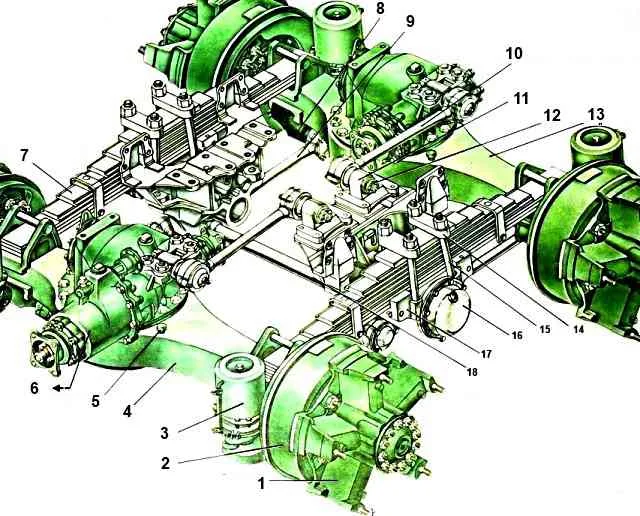
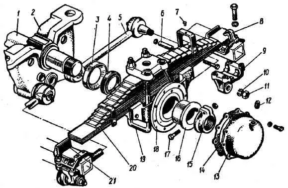
The balance suspension of the intermediate and rear axles of the KamAZ-5320 vehicle is shown in Fig. 1
Rods that pivotally connect the axles to the frame form a lever suspension in the form of a parallelogram
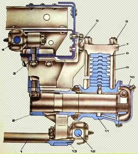
On the brackets attached to the frame side members, the balancer device brackets into which the axle is pressed are secured with studs and nuts.
The shoe can be rotated on an axis in two bronze bushings, held against axial displacement by a split nut tightened with a bolt.
The middle of an inverted semi-elliptical spring is attached to the shoe with stepladders and an overlay.
The ends of the springs are installed on supports.
When the springs bend, their ends slide in the supports.
During the downward movement of the axles, the springs are held in the supports by fingers.
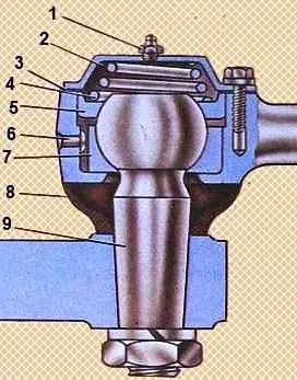
Pushing forces and reactive moments are transmitted to the frame by six reaction rods. The reaction rod hinges are self-clamping.
The ball joint pins are located between the spherical liners 5 and 7.
To seal the hinge against leakage of lubricant and ingress of dirt, an end seal 8 is installed
According to the distance between the centers of the holes in the tips, reaction rods are divided into four selective groups.
Rods of adjacent groups may differ in length by 0.6-1.2 mm.
The lower suspension rods have one group, since with an unfavorable combination of sizes, it is possible to install the intermediate and rear axles at an angle to each other, which increases fuel consumption and causes increased tire wear.
Installation of upper suspension bars by group is not regulated.
The group marking is printed on the head of the rod end and is covered by the hinge seal.
The suspension distributes loads evenly between the intermediate and rear axles, and they can move up and down independently of each other as a result of the rotation of the shoe.
The possibility of relative angular transverse misalignment of axles when a vehicle moves on an uneven road is due to the sliding of the ends of the springs in the supports.
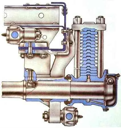
The rear suspension of the KamAZ-53212, -54112, -5511 vehicles, unlike other vehicles, has a balancing device with one axis (Fig. 4), which also serves as a balancer tie.
The springs of this suspension are reinforced and consist of 14 sheets instead of 9.
The first, second, third and last sheets of this spring are of rectangular section, the remaining sheets are of T-shaped section.
To fasten the spring to the shoe, reinforced stepladders 2 are used.
On KamAZ-4310 vehicles, the rear spring step nuts are secured against self-loosening with locknuts.
")

")
")
")
")
")
")
")