This article will cover the removal and installation of the balance shaft, and replacement of the reaction rods
In the previous article, we covered the replacement of the rear suspension springs
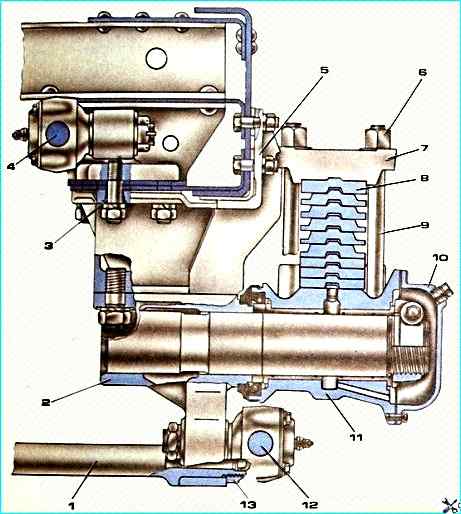
Replacing the rear suspension balance shaft
The balance shaft with the bracket assembly is subject to replacement:
- - in case of radial movement of the spring shoe, which cannot be eliminated by adjusting and replacing the bushings;
- - mechanical damage (breakage, bending of the shaft, cracks in the brackets, etc.)
Removing the balance shaft with the bracket assembly
Remove the rear spring as described in the article "Replacing and repairing springs of a KAMAZ vehicle"
Using a 46 mm open-end wrench, unscrew the nuts of the lower reaction rod pins, remove the spring washers and press the pins out of the balancer axle bracket
Using a 13 mm socket wrench, unscrew the shoe cover bolts, drain the oil into a prepared container and remove the cover with the gasket
Using a 19 mm wrench, unscrew the nut of the spring shoe nut tightening bolt
Unscrew the shoe nut and remove the spring shoe
Using a 55 mm socket wrench, unscrew the balancer axle bracket tie rod fastening nut and loosen the second nut on the opposite end of the tie rod
Install the stands under the balancer axle brackets (we perform this with assistant)
Using a 41 mm socket wrench, unscrew the nuts securing the balance beam axle brackets to the rear suspension brackets
Raise the rear of the car until the rear suspension bracket studs come out of the balance beam axle bracket holes
Remove the axle assembly (do it together with an assistant)
Installing the balance beam axle with the bracket assembly
Install the balance beam axle with the bracket assembly on a stand, putting the bracket on the clamp, and tighten the clamp nuts (do it together with an assistant)
Lower the rear of the car and secure the balance beam axle brackets to the suspension brackets with nuts
Install the shoe bushings, the spring shoe with the cuff and tighten the split nut so that the balance beam does not turn from hands, then unscrew the nut by 1/6 turn and tighten the tie bolt nut with a torque of 78.2-98.1 N m (8-10 kgfm) (performed together with an assistant)
Install the gasket and secure the shoe cover
Pour TSP-15K oil into the shoes to a level of at least 60 mm from the lower edge of the filler hole and tighten the plug
Insert the pins of the reaction rods into the balancer axle bracket and put on the spring washers, tighten the pin nuts with a torque of 353-392 N m (36-40 kgfm)
Install the rear spring "Replacing and repairing springs of a KAMAZ vehicle"
Replacing the reaction rods
The reaction rod is subject to replacement under the following malfunctions:
- - wear of ball surfaces of pins and liners. An external sign of wear is the presence of free play in the ball joints of the rod;
- - rupture, wear of the mud seal;
- - mechanical damage to the rod
Removing the upper reaction rod
Remove several boards of the platform floor
Unpin and unscrew the nut of the ball pin and press it out of the lever of the reaction rod of the rear suspension with a puller
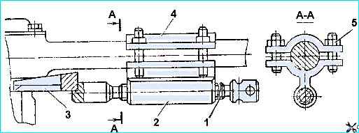
Unscrew the nuts of puller 5, remove cover 4, pass the rod between the studs of the puller
Put cover 4 on the studs and tighten nuts 5
Insert wedge 3 until it stops between the ends of the rod tip and the eye of the finger, while screw 1 should be in the extreme right position
Tighten nuts 5 and, screwing screw 1 into housing 2, press the finger out of the eye
We do the same for the finger of the rod head, fixed in the bracket of the upper reaction rod
Replacement of liners and fingers of reaction rods is carried out if the axial play in the reaction rod is more than 1.3 mm
Installing the upper reaction rods
We install the rod head pin into the upper reaction rod bracket, put on the spring washer and tighten the pin nut with a torque of 353-392 Nm (36-40 kgfm)
We do the same for the rear suspension reaction rod leverki
Lubricate the ball joints of the reaction rod heads through the oilers with Litol-24 grease
Remove the lower reaction rod and install it according to the same scheme
Adjusting the axial clearance in the balance device shoe
Lift the car by the frame and install it on stands.
Ensure the ability to rotate the balancer by separating the ends of the rear spring from the axle supports or by removing the spring
Tighten the split nut so that the balancer does not turn by hand
Unscrew the nut by 1/6 of a turn, tighten the tie bolt with a torque of 78.2-98.1 Nm (8-10 kgfm) and check the ability to rotate the balancer.
If the balancer does not turn, additionally release the split nut, having previously loosened the clamping bolt
When disassembling the balance device, in case of wear of the axles and bushings of the balance device shoes above the permissible limit, it is necessary to grind the axles until traces of wear are eliminated and install repair bushings (reduced in inner diameter).
With a nominal diameter of the balance shaft of 87.93-88.00 mm, the nominal gap between the axle and the bushings should be 0.120-0.305 mm.
The permissible gap between the axle and the bushings without repair is no more than 1.0 mm