Air coming out of the valve during braking is discharged to the outside through the air duct connected to the atmospheric outlet (II)
Disassembling, assembling and adjusting the valve
Install the valve in a vice with soft jaws and secure it by the body 1 (Fig. 1) with the cover 5 facing up.
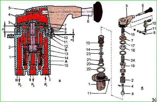
Unscrew the axles 9 of the rollers 11, holding the cover 5 with your hand, and remove it with the spring 16.
Then, using a center punch, carefully knock out the pin 4 and remove the cam of the rod 7 with the washer.
Use round-nose pliers to remove the thrust ring 17 and remove the rod guide 18, springs 2 and 29, the spring plate 19 and the rod 8 from the housing 1.
Release the housing 1 of the tap from the vice and remove the piston 15 with the valve 14 assembled using a wooden mandrel inserted through the atmospheric outlet (III).
To disassemble the valve 14 from the piston 15, use round-nose pliers to remove the thrust ring 20, holding the piston 15 in your hand and being careful, as there is a compressed conical spring 21 in the piston.
After disassembling the brake valve parts of the parking brake system, they must be washed with clean gasoline or acetone, dried and carefully inspected.
There must be no cracks, hairlines or other defects visible to the eye on the surface of the body parts. The parts must be cleaned of rust and burnt-on deposits.
All rubber parts must be replaced with new ones. Springs should be painted with varnish or paint.
Before assembling the faucet parts, lubricate them with a thin layer of TSIA-TIM-221 grease by hand.
Valves, rubber sealing rings and other rubber parts should be assembled carefully, preventing damage.
The presence of scratches, cuts and other defects on the surface of these parts is not allowed.
Assembly of the faucet should begin with the subassembly of valve 14 with piston 15, placing it on a flat table.
Install valve 14, support washer 23 in the piston, orienting its flange to the rubber element of the valve, conical spring 21 and, using round-nose pliers, thrust ring 20.
Then it is necessary to clamp body 1 in a vice and install piston 15 in it in assembly with valve 14 (see Fig. 1).
Install spring 2 with plate 19.
Assemble rod 8 with washer, spring 2, plate 19 and install it in housing 1. Then install spring 24 and rod guide 18, paying attention to the presence of a rubber sealing ring on it.
After this, if necessary, you can adjust the force of spring 2 (see Fig. 2). To do this, compress spring 2 to a size of x = 13.8 ... 13.9 mm from the upper end of housing 1 to the upper end of plate 19. In this case, the spring force should be equal to 130-155 N.
If this force is less than the specified value, install adjusting washers (part. 100-3537095 or 100-3537097), bring the spring force to the required value.
Installing washer 1003537095 increases the spring force by 42.5 N and provides a pressure drop of 0.035 MPa, and installing washer 100-3537097 - by 22.5 N and 0.021 MPa, respectively.
After adjusting the springs, put on rod cam 7 and, being careful, install it into rod 8 using core pin 4. then install spring 16 and cover 5, having first inserted rollers 11 into it. Screw in two axles 9, securing cover 5 with them.
Measure the minimum gap between cover 5 and washer 22, which should not exceed 0.15 mm.
If this gap is larger, then combine adjusting washers part. 100-3537092 0.15 mm thick, part. 100-3537093 0.2 mm thick and part. 100-3537094 0.3 mm thick and place on washer 22 between cover 5 and body 1 so that the gap does not exceed the specified value.
Washer 22 part. 100-3537091 0.5 mm thick remains lying below. The washers must be lubricated with TSIA-TIM-221 grease, GOST 9433-60.
Check the ease of returning the handle to its original position when it is deflected at an angle of 40-45° and 65-70°.
Checking the functionality of the crane
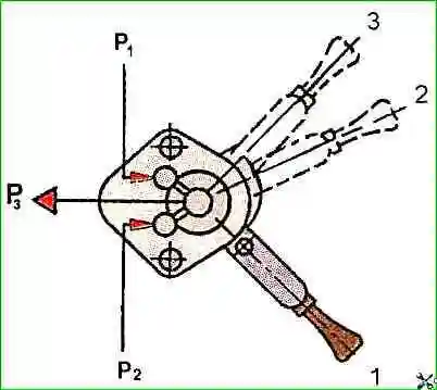
Install the crane on the test bench and connect it according to the diagram shown in rice. 2.
Apply air under a pressure of 0.75 MPa to the outlet, while the pressure in outlet 1 should be equal to the pressure in outlet 1.
Move the tap handle from position 1 to position 3 and back three times.
Then slowly move the tap handle from position 1 to position 3.
When moving the handle, there should be no jamming and it should easily lock in position 3.
When turning the handle from position 1 by an angle of up to 70°, it should automatically return to position 1.
Slowly turn the handle from position 1. When turning the handle by 8-10°, the pressure in outlet (II) should drop, but not more than 0.15 MPa.
With further rotation of the handle, a smooth decrease in pressure in the outlet should occur. (II) to 0.
To check the tap for leaks, air must be supplied under a pressure of 0.75 MPa to the outlet (I) with the handle in positions 1 and 3.
When soaping, the appearance of air bubbles is not allowed for 1 min.
")

")
")
")
")
")
")
")