The fuel supply system ensures fuel purification and uniform distribution among the engine cylinders in metered portions and at strictly defined moments in time
The engines use a split-type fuel supply system consisting of a 337 high-pressure fuel pump with a speed regulator, a fuel priming pump, injectors, coarse and fine filters, a pre-start pump, high-pressure and low-pressure fuel pipes, an electromagnetic valve and EFU flare plugs.
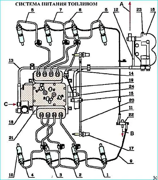
Fuel supply system engine fuel: 1, 8 - high-pressure fuel pipes; 9 - fuel drain pipe of left-hand head injectors; 10 - injector; 11 - fuel drain pipe of right-hand head injectors; 12 - fuel outlet pipe of high-pressure fuel pump; 13 - fuel pump outlet pipe; 14 - fuel supply pipe of high-pressure fuel pump: 15 - EFU valve; 16 - fine fuel filter; 17 - spark plug; 18 - fuel priming pump; 19 fuel supply pipe to EFU valve, 20 - fuel pipe from solenoid valve to pin spark plugs; 21 - high-pressure fuel pump; 22 - tee; 23 - jet valve; 24 - high-pressure fuel pump bypass valve; (A, B) - fuel drain into tank; (C) - fuel supply from the coarse fuel filter
The fuel supply system diagram is shown in Figure 1.
The coarse fuel filter and the pre-start fuel pump must be installed in the fuel supply system of the object where the engine is used.
Fuel from the tank is supplied through the coarse filter and the pre-start fuel pump 18 by the fuel priming pump to the fine filter 16.
From the fine filter, fuel enters the high-pressure fuel pump 21 through the low-pressure fuel pipe 14, which, in accordance with the order of operation of the cylinders, distributes the fuel through the high-pressure pipes 1-8 to the injectors 10. The injectors inject fuel into the combustion chambers.
Excess fuel, and along with it, air that has entered the system through the bypass valve of the high-pressure fuel pump 24 through the pipe 12 and the valve - the jet 23 of the fine filter is diverted to the fuel tank.
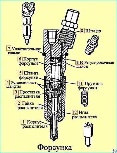
The nozzle (see Fig. 2) is of a closed type, with a five-nozzle nozzle and hydraulic needle lift control mod. 273-31 for engine mod. 740.11-240. mod. 273-21 with a nozzle from OAO "YAZDA" or mod. 273-51 with a nozzle from "BOSCH" for engines mod. 740.13-260 and 740.14-300.
All the parts of the nozzle are assembled in the housing 6. The spacer 3 and the housing 1 of the nozzle, inside which the needle 12 is located, are attached to the lower end of the nozzle housing with a nut 2.
The housing and the nozzle needle make up a precision pair. The atomizer has five spray holes.
The spacer 3 and the housing 1 are fixed relative to the housing 6 by pins 4.
One end of the spring 11 rests against the rod 5, which transmits force to the atomizer needle, and the other end rests against the set of adjusting washers 9, 10.
Fuel is supplied to the atomizer under high pressure through the nipple 8 with a slotted filter 13 built into it, then through the channels of the housing 6, spacer 3 and the atomizer housing 1 - into the cavity between the atomizer housing and the needle 12 and, lifting it, is injected into the cylinder.
The fuel that has leaked through the gap between the needle and the atomizer housing is discharged through the channels in the atomizer housing and drains into the tank through the drain pipes 9 and 11 (see Fig. Engine fuel system fuel).
The injector is installed in the cylinder head and secured with brackets. The end of the nozzle nut is sealed against gas breakthrough with a corrugated copper gasket.
The sealing ring 7 protects the cavity between the injector and the cylinder head from dust and water.
Due to the possibility of engine failure, it is strictly prohibited to install injectors of other models, except those specified in the manual.
On the engine mod. 740.11-240, it is allowed to install injectors mod. 273-21 and 273-51, used on engines mod. 740.13.-260 and 740.14-300
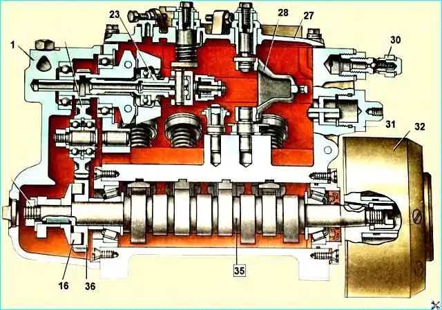
The high-pressure fuel pump (see Fig. High-pressure fuel pump) is designed to supply fuel to the engine cylinders at certain times ы time of strictly metered portions of fuel under high pressure
The 740.11-240 engine is equipped with a fuel injection pump mod. 337-40 with a plunger diameter of 11 mm and a plunger stroke of 13 mm, a reinforced fuel injection pump body with a tunnel for a camshaft of an increased diameter and reinforced bearings, a high-capacity discharge valve with a diameter of 7 mm.
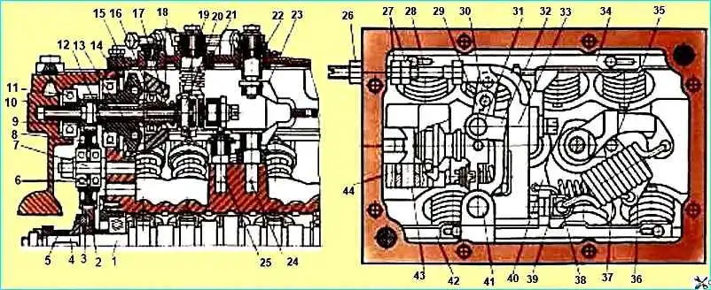
All-mode speed controller: 1 - camshaft; 2 - pinion gear, 3 - rubber crackers, 4 - pinion gear flange, 5 - fuel injection pump drive eccentric, 6,11,12 - ball bearings; 7, 13, 24, 25, 41, 43 - axles; 8 - intermediate gear, 9 - adjusting washers, 10 - rear cover, 14 - retaining ring, 15 - weight holder; 16 - thrust bearing, 17 - weight clutch, 18 - weights; 19 - thrust heel; 20, 31 - pin, 21 - stop lever; 22 - control lever shaft, 23 - spring lever, 26, 27 - nuts, 28 - nominal fuel supply screw, 29 - pins, 32 - clutch lever, 33 - governor lever; 34, 42 - racks, 36 - starting spring lever, 37 - rack lever, 30, 35 - main regulator spring, 38 - adjusting screw, 39 - starting spring, 40 - intermediate rack lever, 44 - roller
The high-pressure fuel pump is equipped with an automatic fuel injection advance clutch (AMOVT) with a nominal rotation angle of the driven half-clutch relative to the leading one of 1 °.
The 740.14-300 engine is equipped with a high-pressure fuel pump mod. 337-80.01 with a plunger diameter of 10 mm and a plunger stroke of 13 mm.
The high-pressure fuel pump is equipped with an automatic control valve with a nominal rotation angle of the driven half-coupling relative to the leading one of 4°30 .
The 740.13-260 engine is equipped with a high-pressure fuel pump mod. 337-42 with a plunger diameter of 11 mm and a plunger stroke of 13 mm. Fuel injection pump without AMOVT.
Eight sections are installed in the fuel injection pump housing 1, which consist of a housing 6, a plunger sleeve 8, a plunger 7, a rotary sleeve 4, a discharge valve 10 pressed against the plunger sleeve by a nipple 11 through a sealing gasket 12.
The plunger makes a reciprocating motion under the action of the shaft cam 35 and the spring 3.
The pusher is fixed from turning in the housing by a cracker 49.
The cam shaft rotates in roller bearings 34 installed in the covers and attached to the pump housing.
The axial clearance of the cam shaft is adjusted by gaskets 33. The clearance should be no more than 0.1 mm.
To increase the fuel supply, plunger 7 is turned by sleeve 4, connected through the axis of the leash to the rack 5 of the pump.
The rack moves in guide bushings 30. Its protruding end is closed by plug 31.
On the opposite side of the pump there is bolt 48, adjusting the fuel supply by all sections of the pump, the bolt is closed by a plug and sealed.
Fuel is supplied to the pump through a special fitting, to which a low-pressure tube 14 is attached with a bolt. Then, through the channels in the housing, the fuel enters the inlet openings of the bushings 8 of the plungers.
At the front end of the housing, where the fuel exits the pump, a bypass valve 29 is installed, which provides pressure in the low-pressure line in operating modes of 0.13-0.19 MPa (1.3-1.9 kgf / cm 2).
The valve opening pressure is adjusted by selecting adjusting washers 50 inside the valve plug.
The pump is lubricated by circulation, pulsating, under pressure from the general engine lubrication system.
The speed controller is all-mode, direct acting, changes the amount of fuel supplied to the cylinders depending on the load, maintaining a given crankshaft speed.
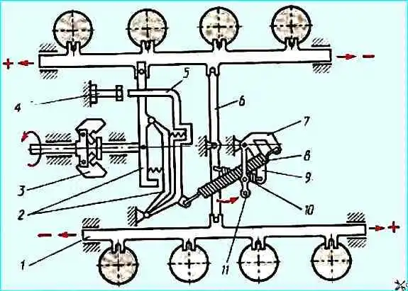
Schematic diagram of the speed controller: 1 - fuel injection pump rack; 2 - weight clutch lever; 3 - holder; 4 - fuel supply adjusting bolt, 5 - regulator lever; 6 - rack lever; 7 - spring lever; 8 - regulator spring; 9 - starting spring lever; 10 - starting spring; 11 - regulator control lever
The regulator is installed in the collapse of the high-pressure fuel pump housing (see fig. High-pressure fuel pump).
The driving gear is located on the camshaft of the pumpe wheel 36 of the regulator, the rotation of which is transmitted through rubber crackers 16.
The driven gear wheel is made as a single unit with the holder 19 of the weights, rotating on two ball bearings.
When the holder rotates, the weights 22, swinging on the axes 20, diverge under the action of centrifugal forces and move the clutch 23 through the thrust bearing 21.
The clutch, resting on the finger 24, in turn, moves the lever of the clutch of the weights 45.
One end of the lever is fixed on the axis 46. and the other is connected to the rack of the fuel pump through a pin.
Lever 11 (Fig. Scheme of operation of the speed regulator) of the regulator control is rigidly connected to the lever 7.
A spring is attached to the lever 7 8. to levers 9 and 6 – starting spring 10.
During the operation of the regulator, the centrifugal forces of the weights are balanced by the force of spring 8.
As the crankshaft speed increases, the weights, overcoming the resistance of spring 8, move lever 2 of the weight coupling with the fuel injection pump rack - the fuel supply decreases.
As the crankshaft speed decreases, the centrifugal force of the weights decreases, and lever 2 with the fuel injection pump rack moves in the opposite direction under the action of the spring force - the fuel supply and crankshaft speed increase.
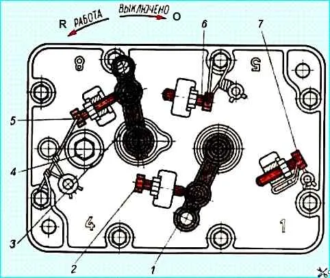
The fuel supply is stopped by turning the lever 3 (Fig. Fuel injection pump regulator cover) of the engine stop until it stops against bolt 6.
In this case, lever 3, having overcome the force of spring 8 (Fig. speed regulator operation diagram), through pin 47 (Fig. Fuel injection pump) will turn levers 2 and 5, the rack will move until the fuel supply is completely stopped.
When the force is removed from the engine stop lever, it will return to the working position under the action of spring 25 (Fig. Fuel injection pump).

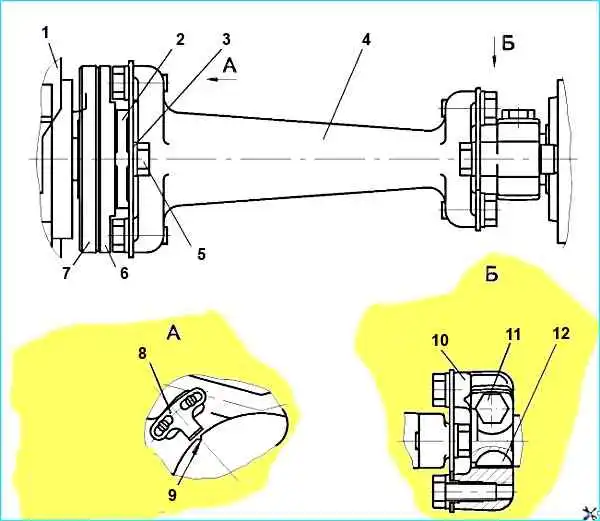
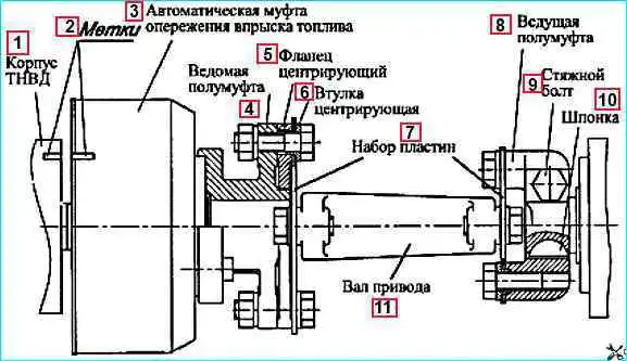
Automatic injection advance clutch: 1 - leading half-clutch; 2, 4 - cuff; 3 - leading half-clutch bushing; 5 - housing; 6 - adjusting linings; 7 - spring cup; 8 spring; 9, 15 - washer; 10 - retaining ring; 11 - weight with pin; 12 - spacer; 13 - driven half-clutch; 14 - sealing ring; 16 - weight axis
Automatic fuel injection advance clutch mod. 333 for engine 740.11-240 and mod. 333-60 for engine 740.14-300 (See figure) changes the start of fuel supply depending on the engine crankshaft speed.
The clutch sets the optimal start of fuel supply for the working process in the entire range of speed modes.
This ensures an acceptable level of emissions of harmful substances with exhaust gases, acceptable efficiency and rigidity of the process at various speed modes of engine operation.
For engines mod. 740.11-240 and 740.14-300 use a high-capacity injection advance clutch with a 25 mm seat cone.
The slave half-clutch 13 is secured to the conical surface of the front end of the fuel injection pump camshaft with a key and a nut with a washer, the leading half-clutch 1 is on the hub of the slave (it can rotate on it).
A sleeve 3 is installed between the hub and the half-clutch.
The weights 11 swing on the axes 16 pressed into the slave half-clutch in a plane perpendicular to the axis of rotation of the clutch.
The spacer 12 of the leading half-clutch rests with one end on the weight pin, and the other on the profile protrusion.
The spring 8 tends to hold the weight in position of the stop in the sleeve 3 of the leading half coupling.
When the engine crankshaft (fuel injection pump cam shaft) speed increases, the weights diverge under the action of centrifugal forces, as a result of which the slave half coupling rotates relative to the leading one in the direction of rotation of the cam shaft, which causes an increase in the fuel injection advance angle.
When the crankshaft (fuel injection pump cam shaft) speed decreases, the weights converge under the action of the springs, the slave half coupling rotates together with the pump shaft in the direction opposite to the direction of rotation of the shaft, which causes a decrease in the fuel injection advance angle.
Checking and adjusting the fuel injection pump, as well as replacing plunger pairs, sealing gaskets of the fuel injection pump sections must be carried out in a specialized workshop and by a qualified specialist.
It is prohibited to install fuel injection pump models that do not correspond to this engine model, due to deterioration in quality tva engine operating process, increasing emissions of harmful substances with exhaust gases, smoke from exhaust gases and to avoid premature engine failure
Reinforced design fuel injection pump drive
The drive is equipped with 5 rear and front plates, each 0.5 mm thick, made of 65G steel.
All bolts in the fuel injection pump drive must be of strength class R100 and tightened with a torque of 6.5-7.5 kgf.m.
The tightening of all bolts must be checked with a torque wrench.
Before installing the bolts, check for the presence of centering bushings.
Spring washers are installed only under the nuts securing the plates to the driven half coupling.
Deformation (bending) of the front and rear plates is not allowed. The tie bolt of the leading half coupling of the high-pressure fuel pump drive is tightened last.
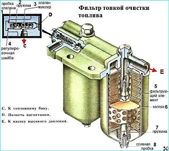
The fine fuel filter (see fig. Fuel filter) finally cleans the fuel before it enters the high-pressure fuel pump.
It is installed at the highest point of the fuel supply system to collect and remove air into the tank along with some of the fuel, through a valve - a jet installed in the filter housing.
At a pressure of 25-45 kPa (0.25-0.45 kgf / cm 2) in the fuel supply cavity, the valve shifts, and at a pressure of 200-240 kPa (2-2.4 kgf / cm 2), the valve opens completely, ensuring the bypass of fuel into the tank.
ATTENTION! When replacing filter elements, it is necessary to strictly observe the rules for servicing the fuel supply system. It is not allowed for contaminants to enter the engine fuel supply system.
Only approved models of filter elements must be used in the fine fuel filter, namely: 740.1117040-01, 740.1117040-02, 740.1117040-04.
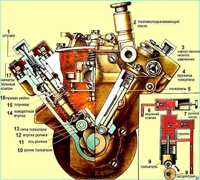
The fuel priming pump 13 (Fig. high-pressure fuel pump) is a piston type, designed to supply fuel from the tank through coarse and fine filters to the inlet cavity of the high-pressure fuel pump.
The pump is installed on the rear cover of the regulator, its drive is carried out from the eccentric of the camshaft of the high-pressure fuel pump.
The pump body contains: piston, piston spring, rod bushing and pusher rod, inlet and discharge valves with springs.
Eccentric The camshaft of the high-pressure fuel pump imparts reciprocating motion to the piston of the low-pressure fuel pump via the roller, pusher 15 and rod.
High-performance fuel priming pump without a hand pump.
The pump operation diagram is shown in the figure below.
When the pusher is lowered, the piston 10 moves downwards under the action of the spring 4.
A vacuum is created in cavity "A" and the inlet valve 3, compressing the spring 2, allows fuel to enter the cavity.
At the same time, the fuel located in the discharge cavity "B" is forced out into the line, bypassing the discharge valve 8, connected by channels to both cavities. In the free position, the discharge valve closes the suction cavity channel.
When piston 10 moves upward, the fuel filling cavity "A" enters cavity "B" under the piston through the discharge valve 8, while the inlet valve closes.
When the pressure in the discharge line increases, the piston does not make a full stroke following the pusher, but remains in a position that is determined by the balance of the fuel pressure force on one side and the spring force on the other.
Pre-start fuel pump piston type serves to fill the fuel system with fuel before starting the engine and to remove air from it.
The pump is installed in the fuel system of the product.
The pump consists of a housing, piston, cylinder, handle assembled with a rod, support plate and seal.
The fuel system should be pumped with a pre-start fuel pump.
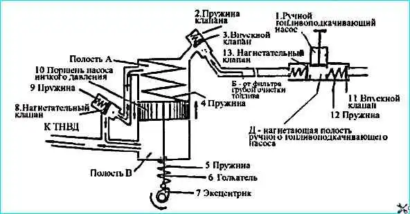
When moving upward, a vacuum is created in the space under the piston.
Inlet valve 11 (see figure), compressing spring 2, opens and fuel enters the pump cavity.
When the handle moves downward, discharge valve 13 opens, and fuel under pressure enters the discharge line, ensuring the removal of air from the engine fuel system through the FTOT nozzle valve and the high pressure fuel pump bypass valve.
After bleeding the system, it is necessary to lower the handle and fix it by turning it clockwise.
In this case, the piston will be pressed against the rubber gasket, sealing the suction cavity of the low pressure fuel pump.
ATTENTION! It is not allowed to start the engine with the handle not locked due to the possibility of air being sucked in through the piston seal.
Fuel pipes are divided into low-pressure fuel pipes - 0.4-2 MPa (4-20 kgf/cm 2) and high-pressure fuel pipes over 20 MPa (200 kgf/cm 2),
Low-pressure fuel pipes are made of steel pipes with a cross-section of 10x1 mm with soldered tips.
High-pressure fuel pipes of equal length (1 = 615 mm) are made of steel pipes with an internal diameter of 2+0.05 mm by upsetting the ends of connecting cones with compression washers and union nuts for connection to the nozzles of the high-pressure fuel pump and injectors.
To avoid breakages from vibration, the fuel pipes are additionally secured with brackets to the intake manifolds.