Installing the cylinder block on the engine assembly stand
Assemble and prepare the piston group
Preparing the crankshaft for assembly.
First you need to install the crankshaft.

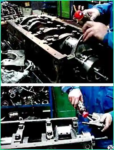
To do this, unscrew the side bolts securing the yokes (main bearing caps) (Fig. 1).

Unscrew the lower bolts securing the yokes (main bearing caps) (Fig. 2).

Take out the yokes and place them in order (Fig. 3).
Wipe the seats of the main bearings.

Lay the upper main bearings with a groove in the middle (Fig. 4).

Lubricate with engine oil and install the pushers into the block sockets (Fig. 5).

Lubricate the upper main bearings with a thin layer of engine oil (Fig. 6).
Place the crankshaft in the cylinder block.

The crankshaft must be laid so that the counterweight of the first cylinder faces down relative to the engine sump (then it fits better) (Fig. 7).

Insert the lower main bearings into the yokes (main bearing caps), lubricate the bearings and install the yokes so that the locks of the bearings coincide (Fig. 8).
Attach the lower bolts of the yokes.
We insert steel-aluminum half rings into the grooves of the rear main bearing so that the side with the grooves is adjacent to the thrust ends of the shaft, and the mustache fits into the groove on the rear main bearing cover.
Pre-tighten the main bearing bolts to a torque of 94.2÷117.7 Nm (9.6÷12kgf.m).

We start tightening from the middle main bearing (Fig. 10), in the order 3-4-5-2-1.
Finally tighten the bolts of the main bearing caps to a torque of 206÷230.5 Nm (21÷23.5).
Screw in and tighten the M12 coupling bolts of the block, ensuring a tightening torque of 80.4÷90.2 Nm (8.2÷9.2 kgf.m).
When tightening with a torque wrench, the resistance should increase smoothly, without jerking. Count the moment as you move the key.
After tightening, the crankshaft should rotate freely from hand force applied to the flywheel mounting pins; the axial clearance in the thrust bearing should be at least 0.05 mm.
For ease of installation of the piston group, turn the block on the stand to a vertical position.
We start installation from the eighth cylinder.

Insert the top one after connecting the connecting rod, lubricate it with a thin layer of engine oil (Fig. 11), and lubricate the cylinder with a thin layer of engine oil.
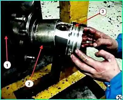
Using a tool for installing the piston group, insert the connecting rod with the piston into the cylinder block, ensuring different locations of the ring locks so that the locks do not coincide on the same axis with the piston pin.
Use the wooden side of a hammer to gently tap the piston, ensuring the correct position of the bolts and the connecting rod liner.

Insert the liner into the connecting rod cover, lubricate the connecting rod and install it so that the locks of the liners coincide (Fig. 13). We tighten the connecting rod cover fastening nuts.
Tightening torque of connecting rod cap bolts with M12 thread to elongation by 0.25÷0.27 mm.
Bolts of reinforced design with M13 thread – 117.7÷127.4 Nm (12÷13 kgf.m).
After this, insert the connecting rod with the piston into the fourth cylinder.
Rotate the crankshaft and insert the piston with connecting rod into cylinders 7 and 3.

Insert the remaining pistons with connecting rods in the same way and tighten with a torque wrench (Fig. 14) to the torque specified above.
Rotate the crankshaft several times.
")

")
")
")
")
")
")
")