The brake pneumatic drive has a source of compressed air - compressor 1. Compressor, pressure regulator 2, fuse 3 against freezing of condensate in compressed air and condensation receiver 11 - the supply part of the drive, from which purified compressed air at a given pressure is supplied to the remaining parts of the pneumatic drive and to other compressed air consumers
The drive is divided into autonomous circuits, separated by safety valves. Each circuit operates independently of the others.
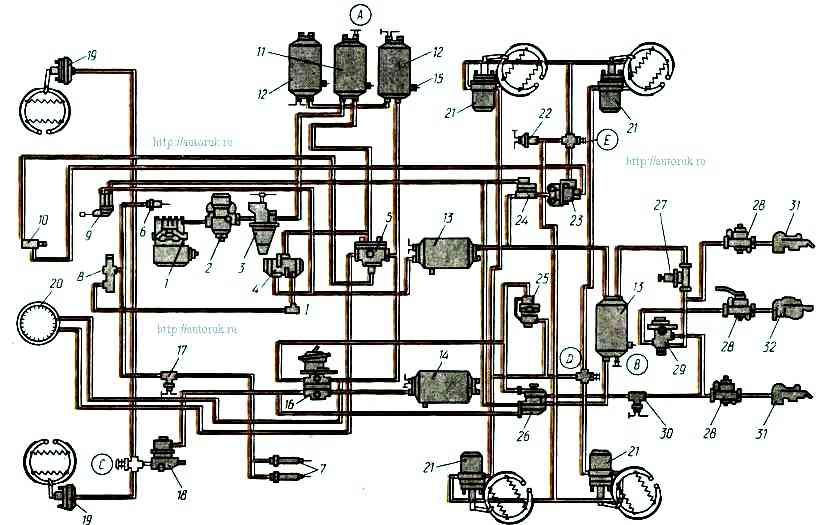
Circuit I of the drive mechanisms of the front axle service brake consists of a part of a triple safety valve 5, a receiver 14 with a volume of 20 liters with a condensate drain valve and a switch for the warning lamp for pressure drop in the receiver, a part of a two-pointer pressure gauge 20, the bottom sections of a two-section brake valve 16, valve C control outlet, pressure limiting valve 18, two brake chambers 19, front axle brake mechanisms, pipelines and hoses between these devices.
In addition, the circuit includes a pipeline connecting the lower section of the brake valve 16 with the valve 26 for controlling the brake systems of a trailer with a two-wire drive.
Circuit II of the rear bogie service brake mechanism drive consists of a part of a triple safety valve, two receivers 12 with a total volume of 40 liters with condensate drain valves 15 and a pressure drop warning lamp switch in the receiver, a part of a two-pointer pressure gauge 20 , the upper section of a two-section brake valve 16, control valve D, an automatic brake force regulator 25 with an elastic element, four brake chambers 21, brake mechanisms.
The circuit also includes a pipeline connecting the upper section of the brake valve 16 with the trailer brake systems control valve 26.
Circuit III of the drive mechanisms of the spare and parking brakes, as well as the combined drive of the brake systems of the trailer (semi-trailer) consists of a part of the double safety valve 4, two receivers 13 with a total volume of 40 liters with a condensate drain valve and a switch control lamp for pressure drop in the receiver, two valves E and B control terminals, parking brake control valve 9, accelerator valve 24, part of a two-line bypass valve 23, four spring energy accumulators 21, parking brake warning lamp switch 22, valve 26 for controlling trailer brake systems with two-wire drive, single protective valve 27, valve 29 for controlling trailer brake systems with a single-wire drive, three disconnect valves 28, three connecting heads (one head 32 type A for single-wire drive of trailer brake systems and two heads 31 type “Palm” for two-wire drive of trailer brake systems ), pneumoelectric brake signal switch 30, pipelines and hoses between these devices.
Circuit IV of the drive mechanisms of the auxiliary brake and other consumers consists of a part of the double safety valve 4, a pneumatic valve 8, two cylinders 7 of the damper drive, a pneumatic cylinder 6 of the engine stop lever drive, pneumoelectric switch 17 of the trailer solenoid valve, pipelines and hoses between these devices.
Circuit IV does not have its own receiver or pressure drop indicator lamp.
From circuit IV of the drive of the auxiliary brake mechanisms, compressed air is supplied to additional consumers via a pneumatic signal, clutch pneumatic booster, transmission unit drives, etc.
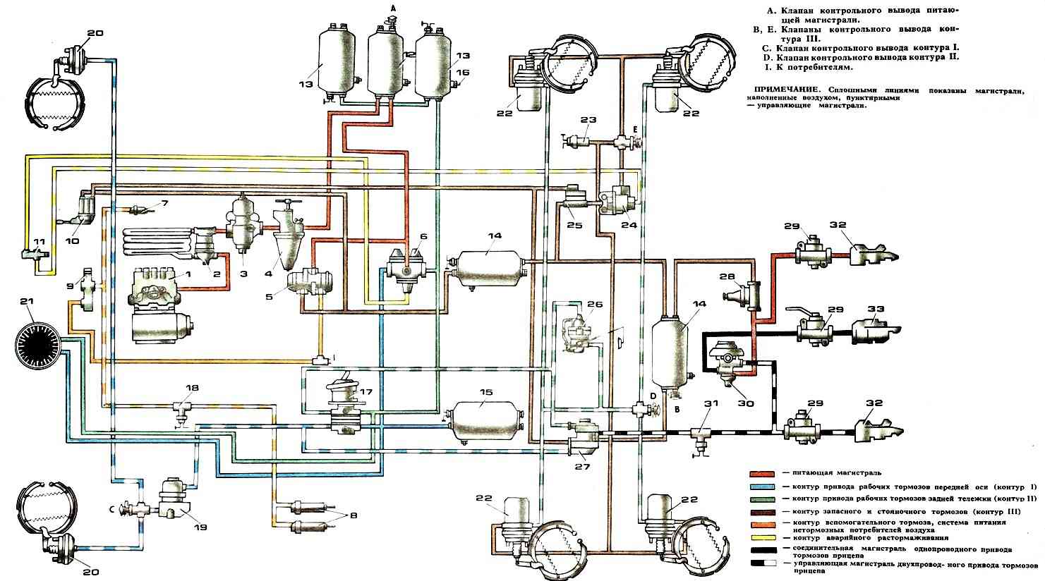
Diagram of the Kamaz-53212 pneumatic drive
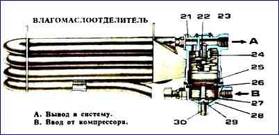
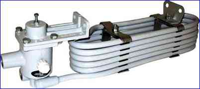
Moisture-oil separator
When describing the components and operating principle, the pneumatic drive of the KamAZ-5320 vehicle was taken as the basis. However, you should be aware that the brake actuators of other cars have their own distinctive features.
To improve moisture separation in the supply part of the brake drive of the KamAZ-53212 vehicle in the compressor-pressure regulator section, a moisture separator is additionally installed on the first cross member of the frame in the zone of intense airflow.
The KamAZ-5511 dump truck does not have trailer brake system control equipment, disconnect valves, or connecting heads.
In addition, for KamAZ-5410, -5511 and 54112 vehicles, the block of protective valves consists of a triple protective valve, through which circuits I and II are filled with compressed air, and a single protective valve, through which circuit III is filled, and circuit IV is filled from circuit I or II.