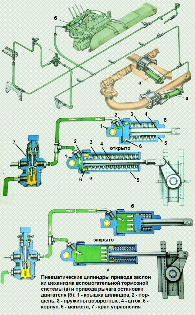
The pneumatic cylinders are the actuators that actuate the auxiliary brake
Three pneumatic cylinders are installed on KamAZ vehicles:
- - two cylinders with a diameter of 35 mm and a piston stroke of 65 mm (Fig. a) for controlling throttle valves installed in the exhaust pipes of the engine;
- - one cylinder with a diameter of 30 mm and a piston stroke of 25 mm (Fig. b) to control the lever of the high pressure fuel pump regulator.

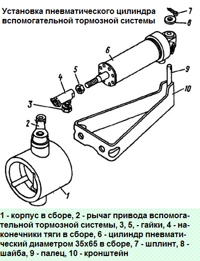
Pneumatic cylinder 035x65 is hinged on the bracket with a pin. The cylinder rod is connected with a threaded fork to the damper control lever.
When the auxiliary brake system is turned on, compressed air from the pneumatic valve through the outlet in the cover 1 (see Fig. a) enters the cavity under the piston 2.
Piston 2, overcoming the force of return springs 3, is mixed and acts through rod 4 on the damper control lever, moving it from the "open" position to the "closed" position.
When compressed air is released, piston 2 with rod 4 returns to its original position under the action of springs 3. In this case, the damper rotates to the "open" position.
Pneumatic cylinder 030x25 is pivotally mounted on the cover of the high pressure fuel pump regulator.
The cylinder rod is connected to the regulator lever by a threaded fork.
When the auxiliary brake system is turned on, compressed air from the pneumatic valve through the outlet in the cover 1 of the cylinder (see Fig. b) enters the cavity under the piston 2.
Piston 2, overcoming the force of return spring 3, moves and acts through rod 4 on the fuel pump regulator lever, moving it to the zero flow position.
The throttle linkage system is connected to the cylinder rod so that the pedal will not move when the auxiliary brake system is applied.
When compressed air is released, piston 2 with rod 4 returns to its original position under the action of spring 3.
Replacing pneumatic cylinders
We replace the cylinders in case of the following faults:
- - cracks, breaks, dents of the cylinder, thread stripping in the threaded hole and on the piston rod;
- - piston rod curvature;
- - air leakage due to wear of sealing rings;
- - breakage or settling of the return spring
Removing the auxiliary brake cylinder

We unscrew the union nut for fastening the pipeline, using a 12 wrench and disconnect it from the pneumatic cylinder fitting
Having unscrewed the nut 3, remove the cylinder 6 as an assembly with the lever 2 of the body 1 of the auxiliary brake system
Removing cotter pin 7, remove washer 8 and cylinder from pin 9 of bracket 10
Unscrew the nut 5, remove the tip 4 from the piston rod of the pneumatic cylinder 6
Installing the auxiliary brake cylinder
We screw the nut 5 and tip 4 onto the piston rod of the pneumatic cylinder 6, tighten the nut 5
We install the cylinder on the pin 9 of the bracket 10, put on the washer 8 and fix it with the cotter pin 7
Connect tip 4 with lever 2 of the auxiliary brake system housing, tighten nut 3
Tighten the union nut that secures the pipeline to the fitting of the pneumatic cylinder
Removing the pneumatic fuel shutoff cylinder
Unscrew the union nut that secures the pipeline to the pneumatic cylinder
We unscrew the nut and unscrew the bolt securing the fuel cut-off rod with the lever
We take out the cotter pin, remove the washer and the cylinder from the bracket pin
Disconnect the rod tip from the piston rod by unscrewing the nut and removing the screw
Installing a pneumatic fuel cut-off cylinder
We attach the rod end to the piston rod of the pneumatic cylinder by inserting the screw and tightening the nut
We install the cylinder on the bracket pin, put on the washer and fix it with a cotter pin
We attach the fuel cutoff rod to the lever, screw in the bolt and tighten the fastening nut
Tighten the union nut that secures the pipeline to the pneumatic cylinder


