Disassembling the diesel engine of a KamAZ-740.10
Before disassembling the diesel engine must be cleaned of dirt and oil, washed with kerosene or a degreasing solution
For washing, it is recommended to use washing solutions MS-6 or MS-8 TU 6-15-978-76 with a concentration of 20-30 g/l at a temperature of 90-100 °C.
Then blow out the diesel engine with compressed air.
Removal of instruments and assemblies from a diesel engine is recommended to be carried out on a stationary rotary stand.
The gearbox must be removed from the diesel engine before installing the diesel engine on the stand.
The rotation of the diesel engine around the horizontal axis of the stand is carried out using a worm mechanism located on the stand.
When disassembling or assembling, the diesel engine must be fixed in any position when braking the worm mechanism.
When disassembling a diesel engine, all parts suitable for further use should be protected from damage
Parts and normal parts removed from the diesel engine should be placed in specially prepared containers in which they are transported for washing, inspection and troubleshooting operations.
Most diesel parts are interchangeable, but some require individual matching with the mating part.
When assembling, parts that have not been repaired or replaced must be installed in their places where they have been worn in.
To do this, they must be marked during disassembly in any way that does not damage the parts.
With the impersonal repair method, it is prohibited to disassemble connecting rod caps with connecting rods, main bearing caps with the cylinder block, since these parts are processed as an assembly.
The crankshaft, flywheel and clutch can be disassembled as these parts are balanced separately.
Disassembly of the diesel engine is carried out in the following sequence:
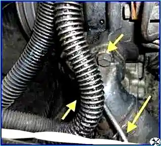
Unscrew the clamp from the expansion tank pipe (Fig. 1).
Unscrew the fastening clamp and remove the expansion tank, if it was not dismantled when removing the diesel engine.
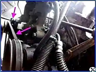
Loosen the tension on the generator drive belt and remove the belt (Fig. 2).
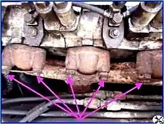
Then, unscrew the nuts securing the exhaust manifold and remove it (Fig. 3).
Remove the gearshift lever support
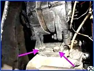
Unscrew the two bolts of the generator bracket and remove the generator (Fig. 4).
Remove the coolant pump.
Remove thermostat housing
Unscrew the bolts and remove the fluid coupling from the front cover of the unit.
Remove the front cover gasket.
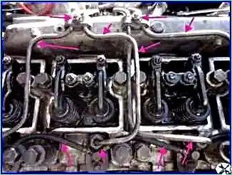
Unscrew the fuel supply pipes from the injection pump (Fig. 5). Remove the injection pump.
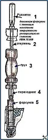
Using a universal puller (Fig. 6) ...
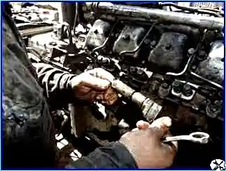
...remove the injectors from the diesel engine (Fig. 7).
Unscrew the inlet pipes and drainage pipes.
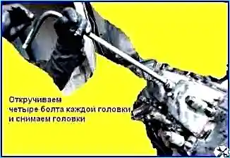
Unscrew the cylinder head bolts, remove the cylinder heads and gaskets (Fig. 8).
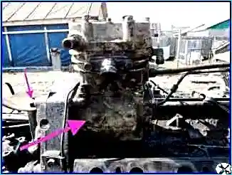
Remove the compressor (Fig. 9).
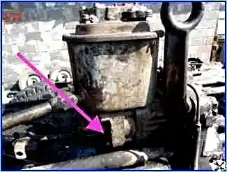
Remove the power steering pump (Fig. 10).
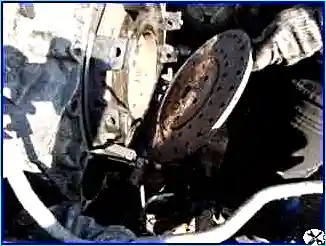
Remove the clutch (Fig. 11).
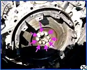
Unscrew the eight bolts securing the flywheel and remove the flywheel (Fig. 12).
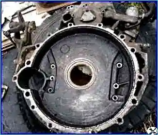
Unscrew the bolts securing the flywheel housing and remove the housing (Fig. 13).
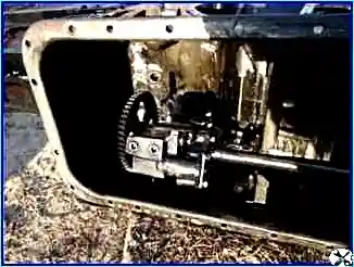
Unscrew the bolts and remove the oil pan and oil pump (Fig. 14).
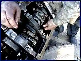
Remove the connecting rod caps with liners; (Fig. 15)
- remove the connecting rods complete with pistons from the cylinders and put the connecting rod caps in their places. See the article “Repair of the connecting rod and piston group.”
When disassembling a diesel engine, the pistons assembled with connecting rods should only be removed upwards. Before removing the pistons, carbon deposits must be removed from the top of the cylinder liner.
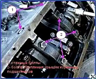
Unscrew the tightening bolts of the yokes 1 (Fig. 16). Unscrew the bolts securing the main bearing caps 2 and remove them together with the liners.

Remove the crankshaft (Fig. 17).
When replacing parts of the sleeve-piston group and the crank mechanism, you must pay special attention to the size groups of the parts.
Remove the compression and oil scraper rings from the pistons using tool I804.03.000.
Remove the retaining rings from the piston bosses using pliers; press out the piston pins.
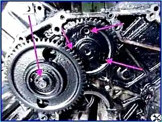
Unscrew three bolts through the holes in the gear, and then, turning the camshaft, remove it from the cylinder block.
Press the cylinder liners out of the block using a tool.
If there is no device, you can knock out the cartridges using an aluminum or bronze drift.
After disassembly, all diesel parts must be washed and blown with compressed air.
Before tightening the main caps, you need to tighten the coupling bolts, and then tighten the bolts of the main caps.
The main caps must be tightened after replacing all the liners; the tightening order matters.
You need to tighten from the middle, from the middle main cap and move towards the edges.
Installation location - Tightening torques
Block pinch bolt 100 – 110 Nm (10 – 11 kgcm)
Cylinder head mounting bolt 190 – 210 Nm (19 – 21 kgcm)
Bolt for securing main bearing caps 210 – 235 (21 – 23.5 kgcm)
Flywheel mounting bolt 150 – 170 (15 – 17 kgcm)
Flywheel housing mounting bolt 90 – 110 (9 – 10 kgcm)
Connecting rod bolt - Up to 0.25 – 0.27 mm extension
After tightening each cap, check the rotation of the shaft.
Rotation should be without tension.


