The brake chamber with a spring energy accumulator type 20/20 is designed to activate the brake mechanisms of the wheels of the rear truck of the vehicle when the service, spare and parking brake systems are engaged.
Spring energy accumulators together with brake chambers are installed on the brackets of the expansion knuckles of the rear bogie brake mechanisms and secured with two nuts and bolts.
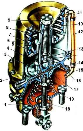
Brake chamber type 20/20 with spring energy accumulator: 1 - housing; 2 - thrust bearing; 3 – sealing ring; 4 - pusher; 5 - piston; 6 - piston seal; 7 - energy storage cylinder; 8 - spring; 9 - screw of the emergency brake release mechanism; 10 - thrust nut; 11 - cylinder pipe; 12 – drainage tube; 13 - thrust bearing; 14 - flange; 15 - brake chamber pipe; 16 - membrane; 17 – support disk; 18 - rod; 19 - return spring
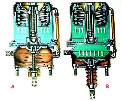
When braking with the service brake system, compressed air from the brake valve is supplied to the cavity above the membrane 16.
The membrane 16, bending, acts on the disk 17, which, through a washer and a lock nut, moves the rod 18 and turns the adjusting lever with the expansion cam of the brake mechanism.
Thus, braking of the rear wheels occurs in the same way as braking of the front wheels with a conventional brake chamber.
When the spare or parking brake system is turned on, that is, when air is released using a manual valve from the cavity under piston 5, spring 8 is unclenched and piston 5 moves down. The thrust bearing 2, through the membrane 16, acts on the thrust bearing of the rod 18, which, moving, turns the associated adjusting lever of the brake mechanism.
The vehicle is braking.
When the brakes are released, compressed air enters through the outlet under piston 5.
The piston, together with the pusher 4 and the thrust bearing 2, moves upward, compressing the spring 8 and allows the brake chamber rod 18 to return to its original position under the action of the return spring 19.
If the gap between the pads and the brake drum is excessively large, that is, if the stroke of the brake chamber rod is excessively large, the force on the rod may be insufficient for effective braking.
In this case, you should turn on the reverse action manual brake valve and bleed air from under the piston 5 of the spring energy accumulator.
The thrust bearing 2, under the action of the power spring 8, will push through the middle of the membrane 16 and advance the rod 18 to the available additional stroke, ensuring braking of the car.
If the seal is broken and the pressure in the parking brake system receiver decreases, the air from the cavity under the piston 5 will escape into the atmosphere through the damaged part of the drive through the outlet and the vehicle will be automatically braked by spring energy accumulators.
The air pressure in the cylinders of energy accumulators depends on the position of the brake valve handle.
If the tightness in the pneumatic drive circuit of the parking (or spare) brake is broken or if the pressure in the receivers of this circuit decreases, automatic braking of the wheels of the rear truck of the vehicle by the springs of energy accumulators may occur.
The movement of the vehicle in this case is ensured by the release of the wheels using a pneumatic or mechanical brake release device.
The device for mechanical release of the brake is made in the form of a screw with a thrust bearing mounted in the pusher tube of the spring energy accumulator.
When the screw rotates, the piston moves along with the pusher, compressing the spring. This releases the rod, which, under the action of the return spring, returns the adjusting lever with the release fist to the released position.
To quickly remove the screw, the tool kit includes a 24X27 socket wrench and a special handle that is inserted into the free end of the wrench to rotate it.
The pneumatic brake release system has an emergency brake release circuit, which consists of a part of a triple safety valve (see compressed air supply II in the figure), a pneumatic valve 8, a part of a two-line bypass valve 7, pipelines and hoses connecting the devices.
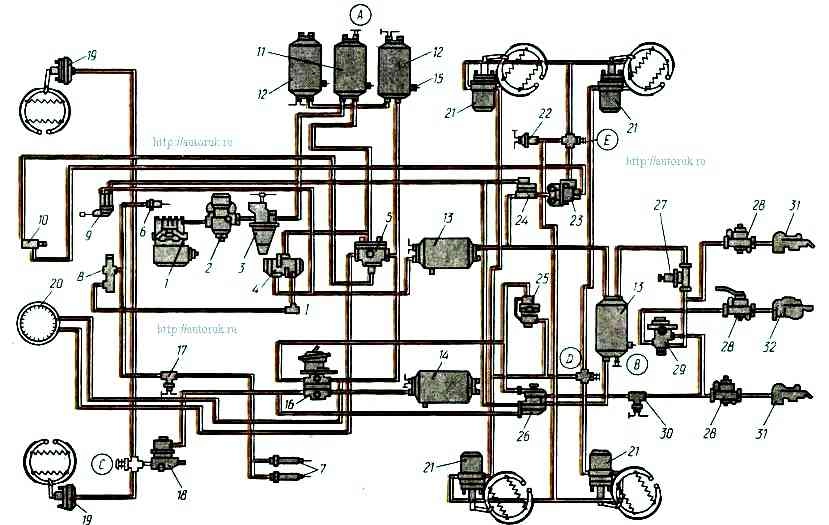
The emergency brake release system drive is powered from the receivers of circuits I and II of the service brake when the pressure in them is more than 500 kPa.
When you press the button of the automatic valve 10, compressed air flows to the auxiliary bypass valve 23 and then to the cylinders of the energy accumulators. The wheels of the rear trolley are released.
The emergency brake release system provides (approximately) three times the full release of the parking brake after emergency self-braking for the purpose of leaving a stop.