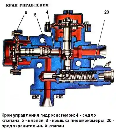
Kamaz hydraulic control valve
The control valve is used to control the flow of working fluid in the hydraulic system.
Saddles 4 and 17 of valves 18 and 5 are pressed into valve body 1, nuts 16 and 10 are screwed in, serving as guides for pushers 15 and 7
The special connection of the valves with the dovetail pushers prevents the valves from jamming in the seats if the axes of the pushers and the seats do not match.
Valves are attached to one end of the pushers, the other ends, on which membranes 13 and 6 are fixed, enter the cavities of the pneumatic chambers closed by covers 14 and 8.
The spring 12 of the pusher 15 holds the valve 18 in the open position, and the spring 9 presses the valve 5 against the seat.
The pushers are sealed with rubber rings 11, and the pusher 7, in addition, has a drainage hole B.

Control valve: 1 - housing, 2, 19 - fittings, 3 - sealing rings of fixed joints, 4, 17 - valve seats, 5, 18 - valves, 6, 13 - membrane, 7, 15 - pushers, 8, 14 - pneumatic chamber covers, 9, 12 - springs, 10, 16 - guide nuts, 11 - sealing rings of movable joints, 20 - safety valve, B - drainage hole, C - collar
In the neutral position, the oil from the pump through the pipeline through the opening of the fitting 19 enters the control valve and, passing through the open valve 18, goes to the drain.
When compressed air is supplied to the cavity of the pneumatic chamber above the membrane 13, valve 18 closes.
At the same time, compressed air enters the cavity of the pneumatic chamber under membrane 6, valve 5 opens.
Oil passes through valve 5, fitting 2 and is directed into the cavity of the hydraulic cylinder.
When air is released from the cavities of the pneumatic chambers, valve 5 closes, and valve 18 opens.
Since valve 5 is closed, the hydraulic cylinder line is closed and the platform is held in a raised position, and oil, when the pump is running, enters it to drain through valve 18 of the control valve.

When compressed air is supplied only to the cavity of the pneumatic chamber under the membrane 6, valve 5 opens and oil from the cavity of the hydraulic cylinder flows through this valve and valve 18 to the drain.
A safety valve 20 is screwed into the valve body, which, when screwed in with collar B, cuts into the body of the valve body and separates the pressure and drain lines.
In the event of an overload, the pressure in the system increases and the safety valve is activated, bypassing the oil into the tank.
Platform lifting will stop until the overload is removed.
The set pressure of the safety valve is adjusted at the factory and cannot be changed during operation.


