Front axles of Kamaz
The front drive axle of the KamAZ-4310 and KamAZ-43105 vehicles, while remaining steerable, at the same time transmits torque to the drive wheels.
Like the rear axles, the front axle consists of a main gear, a differential and axle shafts with constant velocity joints.
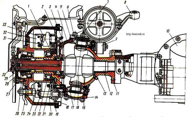
Front drive axle: 1 - steering knuckle axle; 2 - adapter fitting; 3 - screw-in fitting; 4 - steering knuckle; 5 - adjusting gasket; 6, 27 - expansion bushings; 7 - oiler; 8 - steering knuckle lever; 9 - adjustment lever; 10 - main gear; 11 - ball joint; 12 - inner fist; 13 - plug; 14 - fist pad; 15 - joint knuckle liner; 16 - hinge disc; 17, 22, 25 - tapered roller bearings; 18 - shield; 19 - caliper; 20 - pad axis; 21 - locking ring; 23 - pad axle lining; 24 - brake pad spring; 26 - left hub with brake drum; 28 - leading flange; 29 - outer joint knuckle; 30 - air shut-off valve; 31 - expansion fist; 32 - front brake pad; 33 - pad roller
The front drive axle axle shaft is made as one piece with cam 12 (Fig. 1.) and is called the internal cam.
The inner knuckle is connected to the outer knuckle 29 by a cam-type constant velocity joint.
The front drive axle housing is cast integrally with the left short axle housing. The right casing is pressed into the axle housing.
The ball joints 11 of the steering knuckle 4 are attached to the flanges of the casings on studs.
The kingpin is split and made in the form of two tenons welded to the ball joint. The body of the steering knuckle 4 is put on these studs.
Between the tenon and the body there are 17 tapered roller bearings installed.
Axles 1 and brake calipers 19 are attached to the steering knuckle housings with studs.
Inside the trunnion there is an outer knuckle 29, rotating in a bronze bushing.
The wheel is driven into rotation from the outer knuckle 29 through the hub 26 and flange 28.
To lubricate the universal joint, 3 liters are placed in the internal cavities of the steering knuckles. a mixture of transmission oil used for the main gears of drive axles and Litol 24 grease (50% each).
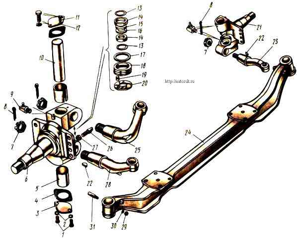
Front axle of cars with wheel arrangement 6X4: 1 - bolts; 2, 30 - spring washers; 3 - lower steering knuckle cover; 4 - cover gasket; 5 - pin bushing; 6 - left front axle steering knuckle; 7, 27, 29 - nuts; 8 - adjustable cotter pin; 9 - oiler; 10 - kingpin; 11 - safety valve; 12 - upper steering knuckle cover; 13 - sealing ring; 14 - oil seal cage; 15 - fist washer; 16 - adjusting washer; 17 - half-ring of the oil seal; 18 - support bearing ring; 19 - pin; 20 - support bearing washer; 21 - right rotary fist; 22 - segment key; 23 - steering knuckle lever to steering linkage rod, right; 24 - front axle beam; 25 - steering knuckle lever to the bipod rod of the steering mechanism; 26 - steering knuckle stop; 28 - steering knuckle lever to the steering linkage rod, left; 31 - wedge pin
The front axle of cars with a 6X4 wheel arrangement is a beam in which steering knuckles 6 and 21 are mounted on pins 10 fixedly fixed in it with wedges 31.
The stamped beam has an I-section, as well as two platforms for attaching springs connecting it to the frame.
The middle part of the beam is curved to ensure a lower engine installation.
The wheel hub, which rotates on two tapered roller bearings, is secured to the knuckle axle using a nut, two lock washers and a locknut.
In order to ensure stabilization of the steered wheels, the axes of the holes for the kingpins are inclined in the transverse plane by 8°, and in the longitudinal plane by 3° back relative to the frame.
The steering knuckles can rotate freely on the pivots thanks to bearings in the form of two bushings 5, pressed into the eyes of the steering knuckles, and a thrust bearing consisting of a support ring 18, a washer 20 and installed between the lower ends of the beam eye and the steering knuckle.</p >
Between the upper ends of the beam eye and the knuckle, washers 15 and 16 are installed, with the help of which the axial clearance in the pivot joint is adjusted.
After installing the kingpin, the holes in the cams are closed with covers 3 and 12 with gaskets 4 to protect the bearings from dirt and dust.
The top cover, unlike the bottom, has a safety valve 11 for the release of lubricant ki.
Levers 25 and 28 are secured in the fists with nuts 7 and cotter pins 8.
The levers against turning in the fists are secured with segment keys 22.
The angles of rotation of the fists are limited by stops 26, which, at maximum rotation, rest against the bosses of the beam.
")

")
")
")
")
")
")
")