Kamaz vehicle clutch
The transmission serves to transmit engine torque to the drive wheels and allows you to change the magnitude and direction of this torque in accordance with the driving conditions of the vehicle
KAMAZ vehicles with 6X4, 6X6 wheel arrangement use a manual step transmission
The mechanical transmission of cars with a 6X4 wheel arrangement consists of a clutch, gearbox, cardan drive, main gears with axle shafts of the intermediate and rear drive axles, and a center differential.
All-terrain vehicles ZMAZ-4310 and KamAZ-43105 with a 6X6 wheel arrangement have three drive axles; in addition to the units listed above, their transmission includes a transfer case, a cardan drive to the front drive axle and the front drive axle itself, consisting of the same mechanisms as the rear ones, and additionally including universal joints for driving the front wheels.
Clutch
The clutch allows you to disconnect the engine from the gearbox and then reconnect it, ensuring gear shifting with minimal shock between the teeth of the connected gears or clutches, as well as smooth starting and acceleration of the car.
In addition, the clutch protects the transmission from being overloaded by inertial torque (during rapid gear changes, sudden changes in vehicle speed, or sudden braking without disengaging the clutch) due to slipping.
The clutch includes a mechanism and a drive.
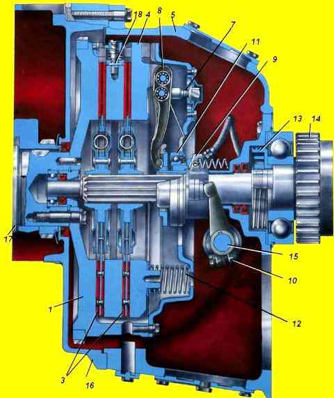
The clutch mechanism (Fig. 1) is installed on the flywheel in crankcase 5. Crankcase 5 is bolted to the engine flywheel housing by the front mating plane.
The clutch is friction, dry, double-disc with peripherally located pressure springs and has a device for automatically setting the middle drive disk to the middle position.
The leading parts of the clutch include flywheel 1, middle drive plate 2, pressure plate 4
The middle drive and pressure disks each have four studs on their outer surfaces, which fit into grooves on the cylindrical surface of the flywheel and receive torque from the engine.
The driven parts of the clutch include two driven disks 3.
The driven disks are steel, equipped with friction linings made of an asbestos composition, each connected to their hubs through a spring-friction type torsional vibration damper (damper), which increases the smoothness of clutch engagement and increases the durability of transmission parts.
The hubs of the driven discs are installed on the splines of the input shaft of the gear divider or gearbox (on vehicles without a divider).
Between the casing 6 and the pressure disk 4, pressure springs 12 are installed, under the action of which the driven disks are clamped between the pressure disk and the flywheel with a total force of 10,200-12,000 N.
The clutch actuating device consists of release levers 8, connected at the outer ends to the pressure plate 4, and in the middle part - with support forks 7, which are installed in the casing 6, a thrust ring 11 of the release levers, a release clutch 9 with a bearing, stopped at the bearing cover of the input shaft of the divider or gearbox, and the release fork 10 mounted on the shaft.
When the clutch is engaged, torque is transmitted from the flywheel through the pin joint to the middle drive and pressure disks, then to the friction linings of the driven disks and through the damper springs to their hubs and then to the input shaft of the divider or gearbox.
When the clutch is engaged, the thrust ring 11 moves away from the clutch bearing 9 by an amount of A = 3.2-4.0 mm, ensuring that the clutch is fully engaged.
When the clutch is disengaged, the clutch 9, through the thrust ring 11, acts on the inner ends of the release levers 8, which rotate on the needle bearings of the support forks 7.
The outer ends of the shutdown levers move the pressure plate 4 away from the rear driven disk 3.
The middle drive disk 2, using an automatic lever mechanism mounted on the disk, also moves and self-aligns into the middle position between the ends of the pressure disk 4 and the flywheel 1, releasing the front driven disk 3.
Thus, between the driving and driven clutch discs when it is completely turned off Gaps are formed that ensure separation of the driving and driven parts and the “cleanliness” of the clutch disengagement.
On turbocharged engines, a model 142 clutch is installed, capable of transmitting torque up to 800 Nm versus 650 Nm on other models.
A distinctive feature of the clutch mechanism of this model is the presence of additional internal springs in the damper of the driven discs and additional pressure springs.
The total force of the pressure springs when the clutch is engaged is 13,150-15,300 N.
To replace the clutch driven discsyou need to remove the gearbox.
Remove the clutch basket.
Before removing the basket, you need to use a core to mark the relative position of the flywheel and the basket.
We place the first driven disk with the long end of the hub facing the engine.

To make the clutch soft, you need to disassemble the basket and remove the internal springs and internal spring plates.


We place the first driven disk with the long end of the hub facing the engine.
We place the second driven disk with the long end of the hub towards the gearbox

Before tightening the basket, center the driven disks using a mandrel or the input shaft of the gearbox
")

")
")
")
")
")
")
")