The operation of the pneumatic drive of the KamAZ-4310 vehicle has the following features.
The supply line includes a compressor 6, a pressure regulator 9 and a moisture separator 8
Compared to other vehicles, the supply line of the KamAZ-4310 vehicle does not have an anti-freeze fuse or a condensation receiver.
There is no need for them, because drying of compressed air is ensured by a moisture separator and by setting the pressure regulator to create a pressure difference between terminals “I” and “III” (see figure) equal to 250 kPa.
This is achieved by having a reinforced check valve spring 9 and an adjusting nut in the regulator.
Check valve 9 operates as a differential valve and opens; with a pressure difference in terminals “I” and “III” equal to 220-280 kPa.
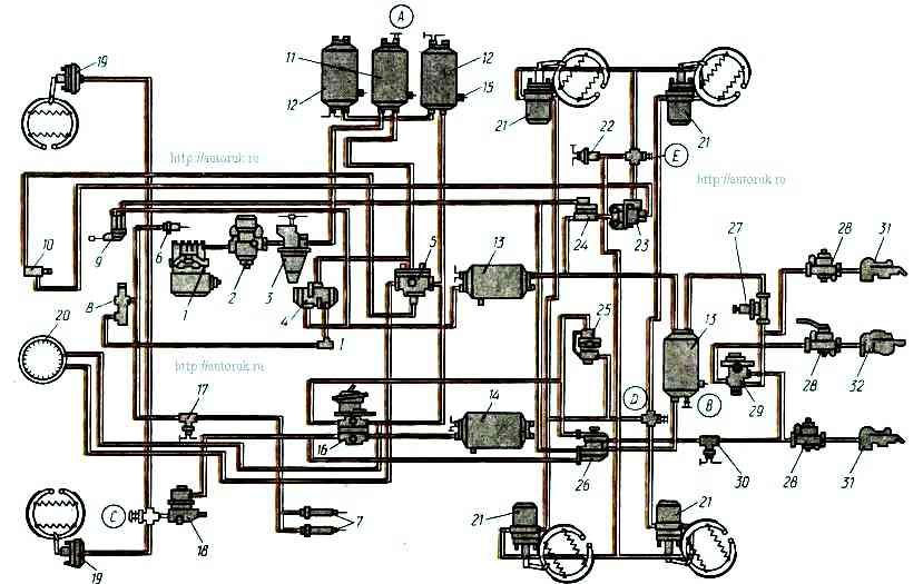
Diagram of the pneumatic brake drive of the KamAZ-4310 car
When check valve 9 opens, the compressed air pressure in the supply line drops sharply.
In this case, a thermodynamic effect occurs, characterized by a decrease in air temperature and the condensation of tiny droplets of moisture in it, which collect in the lower part of the dehumidifier and are automatically released into the atmosphere through its drain valve.
Condensed moisture is also removed through the atmospheric outlet of the pressure regulator when it is opened.
In the block of safety valves* of the KamAZ-4310 vehicle, a single safety valve 70 is used instead of a double one, since the KamAZ-4310 vehicle does not have an emergency brake release system.
On these cars, the pneumatic drive of the parking brake is designed like this; that the release of the energy accumulators of the brake chambers is ensured immediately after starting the engine, regardless of the presence of compressed air in the receivers.
Double-line bypass valves 20 and 21 provide air supply from the control line of valve 7 directly to energy accumulators in the absence of air in receivers 19.
You can therefore start driving after the parking brake warning light goes out.
It should be remembered that if there is no air in the receivers of circuits “I” and “IV” (pressure gauge readings), the service brake system does not operate and braking must be carried out using valve 7.
The pneumatic drive of the service brake is designed almost the same as on other cars.
A special feature is that in circuit “I” of the front axle brake drive there is no pressure limiting valve, and in circuit “II” of the rear bogie brake drive there is no brake force regulator.
In addition, it should be noted that the rear wheels use brake chambers with 24/24 type energy accumulators with an increased active membrane area.
")

")
")
")
")
")
")
")