The accelerator valve supplies compressed air to the energy accumulators and is designed to reduce the response time of the parking and spare brake drive by reducing the length of the compressed air inlet line into the spring energy accumulators and releasing it from them into the atmosphere
It consists of a control chamber 2, a piston 3, an exhaust valve 1 and an intake valve 4, and an intake valve spring 5. Compressed air from the receiver is constantly supplied to terminal III.
Terminal IV is connected to the manual brake valve, terminal I is connected to the cavities of the cylinders of spring energy accumulators, terminal II is connected to the atmosphere.
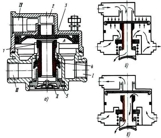
In the initial position, when the car is released (Fig. b), piston 3 is in the lower position, under the influence of compressed air, the exhaust valve 1 is closed, the inlet valve 4 is open, since the area of the upper part of the piston 3 is larger than the area of the lower one, and the pressure in cavity Aand chamber 2 is the same.
The output I is separated from the atmospheric output II, and the pistons of the spring energy accumulators are under compressed air pressure and do not act on the brake chamber rods.
When braking (Fig. 1c), compressed air from chamber 2 is released into the atmosphere through the atmospheric outlet of the hand brake valve.
As the pressure in chamber 2 drops, piston 3 moves upward, inlet valve 4 closes under the action of spring 5, and outlet valve 1 opens.
Through outlet I and the open outlet valve 1, the cavities of the spring energy accumulators communicate with the atmospheric outlet II.
The pressure in the cylinder cavities of spring energy accumulators decreases, the springs expand, and the brake mechanisms are braked.
Release is carried out by supplying compressed air from the tap to terminal IV and then into chamber 2.
Piston 3, moving downwards, first opens exhaust valve 1, then inlet valve 4.
Compressed air comes from the receiver into the cavity of the spring energy accumulators.
The pressure in the cavities of the cylinders of spring energy accumulators increases, the springs are compressed, and the brake mechanisms are released.
The proportionality between the control pressure in terminal IV and the pressure in the cavities of the spring energy accumulators (in terminal I) is maintained by piston 3.
When a certain pressure is reached in the outlet I, the piston 3 moves up to the closed inlet valve 4, moving under the action of the spring 5, and further pressure growth stops.
When the pressure in port IV decreases, piston 3, under the influence of higher pressure in port I, moves upward and breaks away from outlet valve 1.
Compressed air from the cavities of spring energy accumulators escapes into the atmosphere through open valve 1 and atmospheric outlet II, the pressure in cavity A decreases.
Replacing the relay valve
The relay valve must be replaced if the following malfunctions occur:
- - violation of valve tightness. An external sign is air leakage through the terminals where the cover is attached to the valve body;
- - mechanical damage to the valve body, cover and pistons, interfering with its operation
Tools needed: wrenches 22x24, 17x19, 12x13, spanner 13x17, vice
Removing the relay valve
We prepare the car and bleed air from the receivers of the 19th circuit of the parking system

Diagram of the pneumatic drive of the brake systems: 1 - brake chambers type 24; 2 - pressure gauge; 3 - auxiliary brake system control valve; 4 - pneumoelectric switch for the trailer solenoid valve; 5 - pneumatic cylinder for driving the engine stop lever; 6 - compressor; 7 - parking brake system control valve; 8 - water separator; 9 - pressure regulator; 10, 28 - single protective valves; eleven - triple safety valve; 12 - two-section brake valve; 13 - pneumatic cylinders for driving the flaps of the auxiliary brake system mechanism; 14 - circuit receiver; 1.15 - pressure drop warning lamp switches; 16 - circuit receivers; 11.17 - condensate drain taps; 18 - consumer receiver; 19 circuit III receivers; 20 - dual-line bypass valve for emergency brake release; 21 - two-line bypass valve; 22 - accelerator valve; 23 - switch for the parking brake system warning lamp; 25 - brake chambers; 24 - control valve for the brake systems of a trailer with a two-wheel drive; 26 - brake signal warning lamp switch; 27 - control valve for trailer brake systems with a single drive; 29 - disconnect valves; 30 - connecting heads of the "Palm" type; 31 - connecting head type A; A, B, C, D - valves of control terminals; P - to the supply line of the two-wheel drive; R - to the connecting line of the single-drive drive; N - to the brake (control) line of the two-wheel drive
Unscrew the union nuts of the pipelines connected to the terminals of the accelerating valve 22 and the dual-line valve 20
Unscrew the nuts securing the accelerator valve bracket to the frame. Disconnect the pipelines from the valve terminals and remove valve 22 together with valve 20 and bracket
Disconnect the accelerator valve from the bracket by unscrewing the bracket nuts
Disconnect valve 20 with passage fitting from valve 22
Installing the relay valve
Install the bracket on the valve and secure it with nuts, attach the two-line valve 20 together with the feed-through fitting
Install the assembled valve with bracket onto the frame and secure it with nuts
Insert the pipelines into the valve terminals, tighten the union nuts of the pipelines and secure the valve to the bracket to the frame
Tighten the union nuts of the pipelines on the valve terminals
Start the engine and create pressure in the pneumatic drive of the brake systems
Check the tightness of the pipelines and the relay valve. Air leakage is not allowed
Checking the operation of the accelerator valve when braking and releasing the car
Repair of accelerator valve
Tools needed: a vice with soft jaws, a 13x17 socket wrench, special pliers I801.23.000-01, utensils for washing parts
Disassembly of the accelerator valve
Installing the valve in a vice
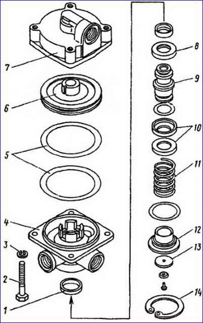
Unscrew the bolts 2 with washers 3 securing the upper housing 7 to the lower housing 4
Remove the upper body from the vice
Remove the thrust ring 14 from the lower housing 4, housing 9 with inlet and outlet valves, spring 11, guide cap 12
Remove the lower body 4 from the vice
Remove piston 6 with sealing rings 5 from the upper housing 7
Note: apply compressed air to the valve cover and remove the piston
We wash the valve parts in diesel fuel and blow with compressed air
Assembling the relay valve
Install the lower body 4 in a vice
Install into body 4 guide cap 12, spring 11, body 9, ring 8, cap 10, valve 13, thrust ring 14
Install into housing 7 complete with piston 6
We screw in the bolts 2 securing the housing 7 of the cover to the housing 4 with spring washers 3
Remove the valve from the vice
We test the relay valve for operability and tightness
Order of tests:
- connect the device according to the diagram shown in the figure
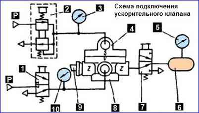
- - open valve 7. Using precision control valve 2, set pressure on pressure gauge 3 to 736 kPa (7.5 kgf/cm 2).
There should be no air leakage from the outlet window 8 of device 4 and through the switched on valve 7. Close valve 2 fine control
- - open tap 1. Air leaks from outlet window 8, device 4 and through tap 7 should not be on. Close tap 7
- - quickly open and close valve 2 for precise control three times. In this case, on pressure gauge 5 the pressure should change from 0 to 736 kPa (7.5 kgf/cm 2) and back
- - slowly increase the pressure on pressure gauge 3 using fine control valve 2. When the pressure on pressure gauge 3 reaches 29.4-44.1 kPa (0.3-0.45 kgf/cm 2), pressure gauge 5 should begin to show pressure
- - increase the pressure on pressure gauge 3 to 736 kPa (7.5 kgf/cm 2). In this case, the pressure on pressure gauge 5 should increase synchronously. With a pressure on pressure gauge 3 equal to 647-687 kPa (6.6-7.0 kgf/cm 2), the pressure on pressure gauge 5 should be equal to 716.1 kPa (7.3 kgf/cm 2)
- - using precision control valve 2, we slowly reduce the pressure on pressure gauge 3 to 0, on pressure gauge 5 the pressure should synchronously drop to 0
The stepwise change in pressure during all tests should not exceed 19.6 kPa (0.2 kgf/cm 2)
During testing, there should be no air leakage from devices 4 at any pressure at terminal S.
")

")
")
")
")
")
")
")