Daily service. Get it right:
- — oil level in the engine crankcase;
- —liquid level in the cooling system.
Service 1:
- —drain sediment from coarse and fine fuel filters;
- —Lubricate the water pump bearings.
Service 2
Check:
- — tightness of the engine air supply system;
- — state and action of the radiator shutters;
- — state and action of the manual fuel control cable;
- - state and action of the engine stop cable;
- — state of the regulator link plate (no deep grooves in the plate window).
Pin:
- —engine oil sump;
- - centrifugal oil filter rotor nut;
- - turbochargers, exhaust manifolds, nozzles and exhaust pipes of the muffler;
- - turbine and compressor housings to the bearing housing.
Adjust:
- - drive belt tension;
- - thermal clearances of the valves of the gas distribution mechanism, having previously checked the tightening torque of the cylinder head bolts and nuts of the rocker arms.
For the KAMAZ-7403.10 engine, change the oil (when using substitutes, change the oil after one Service 1).
For all types of maintenance, check for leaks from the drain and oil supply line to the turbochargers.
If necessary, replace the O-rings of the turbocharger oil drain line.
Service С
Pin:
- —radiator;
- - flanges of intake pipes, muffler pipes.
Adjust:
- —lifting pressure of the nozzle needles on the stand;
- —fuel injection advance angle.
Change:
- —filter element with a precleaner;
- — coolant (TOSOL A-40).
Optional in autumn:
- check on the stand, troubleshoot and maintain the high pressure fuel pump (TNVD).
To check the oil level, install the car on a horizontal platform, stop the engine and after holding for 4 ... 5 minutes, the oil level on the dipstick should be near mark B.
Change the oil in the crankcase, clean the centrifugal filter rotor and change the oil filter elements in the following order:
- warm up the engine to a coolant temperature of 70 ... 90 ° C, stop the engine and drain the oil by unscrewing the drain plug from the crankcase; screw the plug after draining the oil;
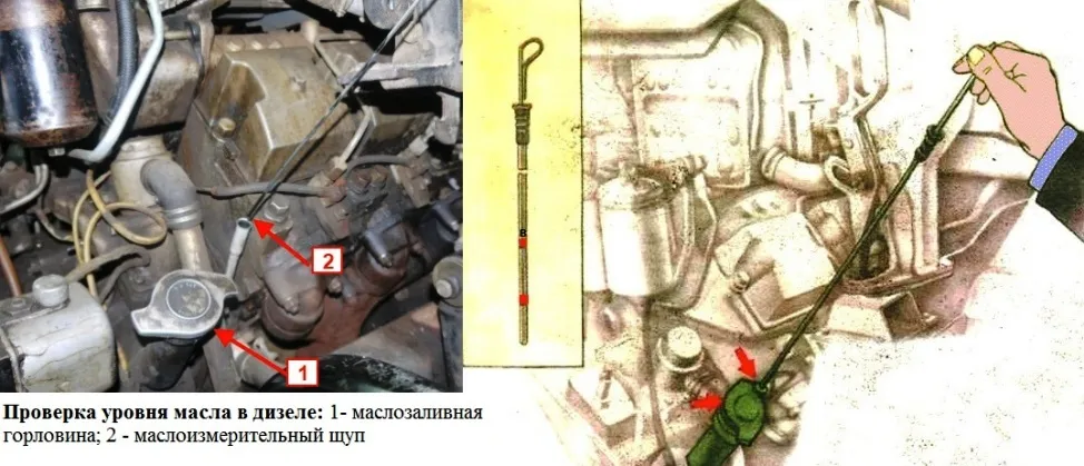
- - open the neck 1 (Fig. 1), having previously cleaned it of dust and dirt;
- - fill oil up to the B mark on the oil level indicator 2;
- - start the engine and let it run for 5 minutes at a low speed to fill the oil cavities;
- —stop the engine and after holding for 4...5 minutes add oil to mark B.
To change the filter elements of a full flow oil filter:
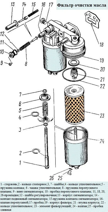
- - unscrew the drain plugs on the caps and drain the oil from the filter into a lined dish;
- — unscrew the bolt securing the filter cap and remove the cap together with the element;
- — remove the filter element from the cap;
- - in this order, remove the second cap and filter element;
- —wash the filter caps with diesel fuel;
- - replace filter elements and assemble the filter; check for oil leaks at the filter connections with the engine running.
In case of leakage, tighten the cap bolts. If the leak on the seal of the caps is not eliminated by tightening the bolts, replace the rubber seals;
- - after replacing the filter elements, bring the oil level to normal.
To wash the centrifugal filter rotor:
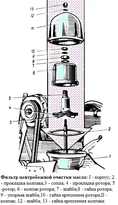
- — unscrew the nut of the filter cap and remove the cap;
- — turn the rotor around the axis so that the locking pins enter the rotor hole;
- - unscrew the nut securing the rotor cap, remove it;
- - check the tightening of the rotor fastening nut on the axle, if necessary, tighten it with a torque of 78.5 ... 88.3 Nm (8 ... 9 kgf.m). Not remove the rotor for maintenance;
- - remove sediment from the caps and wash them with diesel fuel;
- - assemble the filter by matching the marks on the cap and the rotor.
Before installing the outer cap, depress the pins of the locking device and check the rotation of the rotor on the axis, the rotor should rotate easily, without jamming.
Tighten the cap nuts with a torque of 19.6-29.4 Nm (2-3 kgf.m).
When servicing an oil cooler, the main defects of which are cavity contamination and oil leakage, clean it by blowing and flushing with hot 10% caustic soda solution, hot water, then kerosene in the opposite direction to air and oil flows.</p >
For flushing with caustic soda solution, use equipment that circulates the liquid.
Check the tightness by filling the radiator with oil under pressure not exceeding 196 kPa (2 kgf/cm2).
If a leak is found, replace the radiator.
At maintenance - 2 (Service 2)
change the filter elements of the fine fuel filter, for this:
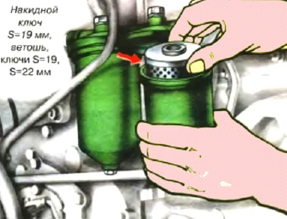
- - unscrew the drain plugs two or three turns and drain the fuel from the filter into the prepared dishes. Then we twist the plugs;
- - unscrew the bolts of the filter caps and remove the caps
- - remove dirty filter elements;
- - wash the caps with diesel fuel;
- - install a new filter element with gaskets in each cap;
- - install caps with elements and tighten bolts;
- - start the engine and check the filter tightness
We eliminate fuel leakage by tightening the cap bolts.
Rinse the coarse fuel filter, to do this:
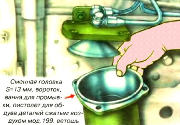
- - drain the fuel from the filter by loosening the drain plug;
- - unscrew the four bolts securing the glass to the filter housing and remove the glass together with the flange;
- - turn the filter element out of the body;
- - we wash the filter element mesh and the cavity of the glass with gasoline or diesel fuel and blow it with compressed air;
- - we put a sealing washer, a distributor on the filter element and screw the filter element into the housing;
- - install the filter cup and fix it with bolts;
- - tighten the drain plug;
- - start the engine and check that there is no air leakage through the filter.
Clean the air cleaner paper element, precleaner and hopper, to do this:
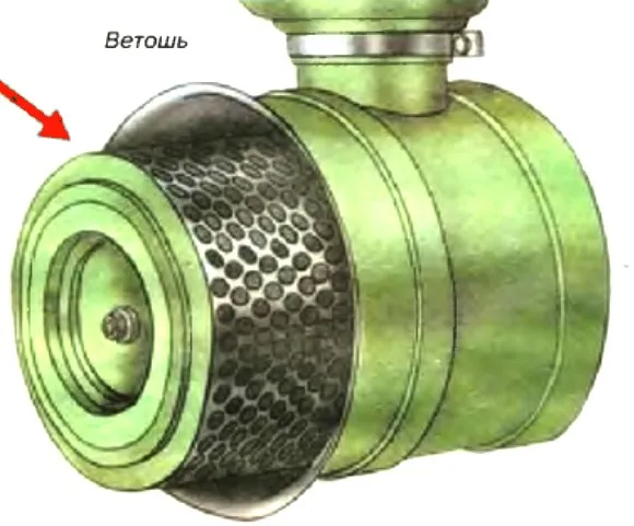
To remove dust, remove the cover, unscrew the three fastening nuts, unscrew the plugs from the holes in the partition, remove dust and wipe the hopper.
The cover must be installed so that the arrow is pointing up when the air cleaner is horizontal (cars models 55111, 5410, 54112).
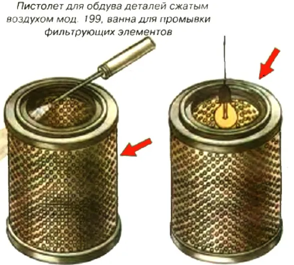
The filter element and the pre-cleaner can be cleaned by blowing or washing, having previously removed the pre-cleaner from the filter element.
Purge is effective in case of dust pollution without soot.
For purging, it is necessary to direct dry compressed air inside the filter element at an angle to the surface of its inner casing at a pressure of no more than 3 kgf/cm2. The element must be blown until dust is completely removed.
Clean the precleaner by shaking or blowing.
To check the condition of the filter element cardboard, you need to illuminate it from the inside with a lamp and inspect the cardboard through the holes in the outer casing.
For convenience, the filter curtain can be moved apart. If there are gaps or other through damage to the cardboard, the element must be replaced.
Flushing the air filter element
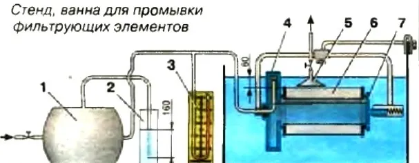
Rinsing is used when the pre-cleaner and filter board are contaminated with dust, soot, oil, fuel.
Rinse the filter element in a warm (temperature 40-50 °C) aqueous solution of neutral detergents (20-25 g of powder per 1 liter of water), followed by rinsing in clean water.
Since rinsing leaches phenolic resins from the filter curtain cardboard, as a result of which the strength of the cardboard decreases, it is recommended to wash the filter element no more than 3 times.
After washing, it is recommended to check the filter element by pressing it with compressed air in water in the following order: install the wet filter element 6 between covers 4 and 7, then immerse it in water to a depth of 60 mm.
Before testing or directly in the test facility, soak the dry filter element in water for 5-10 minutes to fill the pores in the cardboard with water;
- - supply air under pressure 1.6 kPa (160 mm water column) to the air cylinder 1 and thus inside the element. This pressure is maintained by a constant liquid valve 2, the tube of which is immersed in water to a depth of 160 mm and is controlled by a pressure gauge 3.
In order to avoid destruction of the filter curtain element, the air pressure should not increase even briefly above 2.0 kPa (200 mm of water column);
- - slowly rotate the element, paying attention to the release of air bubbles from its outer surface;
- - bring a transparent cap 5 filled with water to the place where air bubbles are released and measure the time it takes to fill it with air.
When filling a cap with a volume of 0.5 l in less than 20 seconds, discard the filter element through one damage.
Dry the serviceable filter element, as well as the precleaner, thoroughly before installing it on the car.
Do not dry with an open flame or hot (temperature above 50 °C) air.
When installing the filter element and precleaner on the car, check the integrity of the rubber gaskets.
It is not allowed to contact the outer casing with the precleaner (the casing can be straightened).
If, after servicing the filter element and the precleaner by washing or blowing, the clogging indicator is triggered when the vehicle has run less than before the next TO-1, replace the filter element and the precleaner.
Once a year, check the accuracy of the air cleaner clogging indicator.
If the vacuum deviation at the moment the indicator is triggered is more than 0.5 kPa (50 mm w.c.) from the vacuum set for the engine of 7.7 kPa (700 mm w.c.), replace the indicator.
Adjust the lifting pressure of the nozzle needles on the stand (once a year).
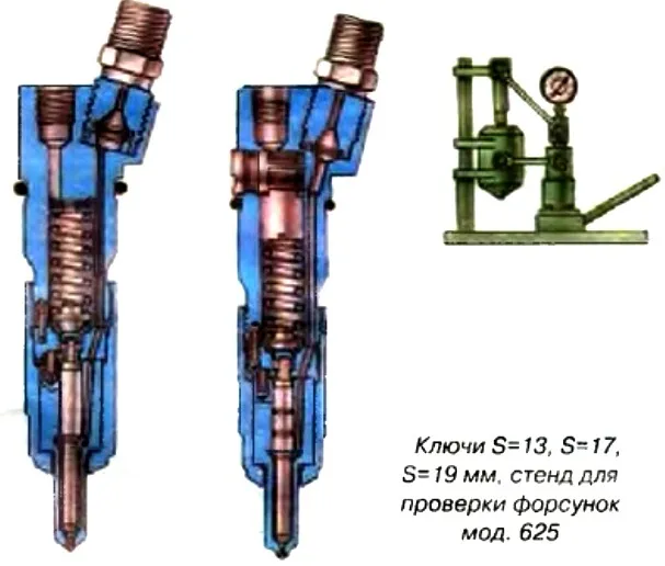
It is adjusted on the stand by installing shims under the spring with the nut, atomizer, spacer and rod removed. By increasing the total thickness of the shims (increasing spring compression), the needle lifting pressure increases.
A change in the thickness of the washers by 0.05 mm leads to a change in the pressure at the beginning of the needle lift by 0.3-0.35 MPa (3-3.5 kgf/cm2). The number of washers to be installed should be no more than three.
Needle lift pressure for motor mod. 740.10 must be within 20.0-22.7 MPa (200-227 kgf/cm2), for engine mod. 740.10-20 - 21.5-24.8 MPa (215-248 kgf/cm2), for engine mod. 740.11 - 19.61-22.36 MPa (196-22 kgf/cm2), for engine mod. 7403 - 21.5-24.2 MPa (215-242 kgf/cm2).
The start and end of fuel injection must be clear.
The sprayer must be free of leaks. The injection should be accompanied by a characteristic sharp sound.
Replacement of any one part (atomizer body or needle) is not allowed, as they make up a precision pair.
Adjust fuel injection advance angle
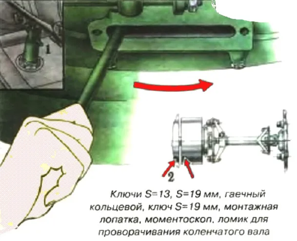
To check and adjust the fuel injection advance angle, after turning off the fuel supply and braking the car, perform the following operations:
- 1). Through the hatch in the lower part of the clutch housing, turn the crankshaft with a crowbar inserted into the hole on the flywheel until the mark on the injection pump housing aligns with the mark of the automatic fuel injection advance clutch.
- 2). Turn the engine crankshaft half a turn against the direction of rotation (clockwise when viewed from the flywheel side).
- 3). Install retainer 1 flywheel and to the lower position and turn the crankshaft in the direction of rotation until the latch enters the flywheel groove.
If at this moment the marks 2 on the injection pump housings and the automatic clutch are aligned, then the injection advance angle is set correctly; the latch is then moved to the upper position.
- 4). If the labels do not match, you must:
- - loosen the upper bolt of the driven half-coupling of the drive, turn the crankshaft in the direction of rotation and loosen the second bolt;
- - turn the fuel injection advance clutch behind the flange of the driven half-coupling of the drive in the direction opposite to its rotation, until the bolts stop against the walls of the grooves (the working direction of rotation of the clutch is right-handed, when viewed from the drive side);
- - lower the latch to the lower position and turn the engine crankshaft in the direction of rotation until the latch aligns with the flywheel groove;
- - slowly turn the fuel injection advance clutch behind the flange of the driven half-coupling of the drive (only in the direction of rotation) until the marks on the injection pump housings and this clutch coincide;
- - fasten the upper bolt of the drive coupling half, set the latch to the upper position, turn the crankshaft and fasten the second bolt.
- 5). Check if the injection advance angle is set correctly (as indicated in point 3).
Check on the stand, troubleshoot and carry out maintenance of the injection pump, change the oil in the fuel injection advance clutch.
The angle of the start of fuel supply by the eighth section of the injection pump to the axis of symmetry of the cam must be 42°±30.
The deviation of the start of fuel supply by the sections of the high pressure pump relative to the eighth section of the pump should not exceed ±0° 30 .
The average cyclic fuel supply at a pump camshaft speed of 1290-1310 rpm with the regulator control lever resting on the maximum speed limit bolt should be within 75.0-77.5 mm3 / cycle.
The uneven supply by sections should not exceed 5%.
The rotational speed of the camshaft, corresponding to the starting flow of the pump sections when the regulator control lever rests on the maximum speed limit bolt, should be 280-330 rpm.
Before installing the injection pump on the engine, turn the crankshaft until the mark on the rear flange of the drive coupling half is in the upper position, and the latch enters the recess on the flywheel.
Install the pump, matching the marks on the pump housing and the fuel injection advance clutch.
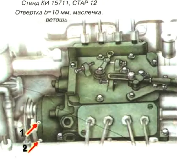
Change the oil in the fuel injection advance clutch when servicing the injection pump at the stand. Pour oil into the clutch housing through the upper hole 1 until oil appears from another hole 2.
In summer:
- M-10G2(k) oil, GOST 8581-78 (at temperatures above +5°C).
- Ufalub Diesel oil SAE-30, TU 0253-003-11493112-93 (at temperatures above +5°C).
- M-10-D(m) oil, GOST 8581-78 (at temperatures above +5°C).
In winter:
- M-8G2(k) oil, GOST 8581-78 (at temperatures above +5°C).
- M-8-D(m) oil, GOST 8581-78 (at temperatures below +5°C).
All season:
- VELS SUPER TURBO oil, TU 38.00148636-60-92.
- Motor oil Ufalub HD Extra, TU 0253-003-11493112-93.
- DV-ASZp-10V oil, OST 38.01370-84.
Adjust the thermal clearances of the gas distribution mechanism, after checking the tightening of the cylinder head bolts and nuts of the rocker arms
To do this, you need tools: Device And 801.14.000 for adjusting valves, a set of probes No. 2, heads S = 17.19, a crowbar for turning the crankshaft, a torque wrench.
Gap value on a cold engine:
- - for inlet valve - 0.25 - 0.30 mm;
- - for exhaust valve - 0.35 - 0.40 mm.
For 1, 2, 3 and 4 cylinders, the front valve is inlet, and for 5,6, 7 and 8 cylinders - exhaust.
Gap adjustment should be done on a cold engine or after stopping the engine, not earlier than after 30 minutes. In this case, the fuel supply must be turned off.
Thermal gaps are adjusted simultaneously in two cylinders, following the order of operation one after the other, during the compression strokes (stroke) in these cylinders. The valves of the adjustable cylinders must be closed at this point.
When adjusting, the crankshaft is set sequentially to positions 1 ... 4, which are determined by its rotation relative to the position of the start of fuel injection in the the first cylinder by the angle shown below:
- - crankshaft position 1 - 2 - 3 - 4;
- - angle of rotation, degrees - 60 - 240 - 420 - 600;
- - numbers of cylinders of adjustable valves 1; 5, 4; 2, 6; 3, 7; 8.
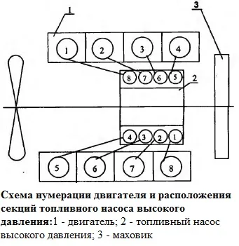
The numbering scheme of the engine cylinders and injection pump is shown in Figure 12.
The sequence of operations when adjusting the gaps is as follows:
- - remove cylinder head covers;
- - check the tightening of the cylinder head bolts;
- - pull the latch mounted on the flywheel housing, turn it 90 ° and set it to the lower position;
- - remove the manhole cover at the bottom of the clutch housing (to crank the flywheel with a crowbar);
- - turning the crankshaft in the direction of rotation, set it to a position in which the latch engages with the flywheel under the action of the spring.
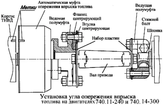
740.11-240 engines. 740.14-300 (740.11-3902001РЭ):
In this case, the marks on the end face of the body of the automatic fuel injection advance clutch and the flange of the driven half-coupling of the high-pressure fuel pump drive must be in the upper position
Engines 740.13-260 (740.11-3902001RE):
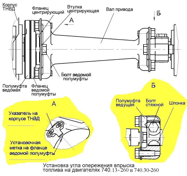
In this case, the pointer on the injection pump housing and the installation mark on the flange of the driven half-coupling of the injection pump drive must be aligned
Engines 740.30-260. 740.50-360. 740.51-320
The pointer on the injection pump housing and the mark on the flange of the coupling half of the driven drive of the injection pump must match
This position of the crankshaft corresponds to the beginning of the fuel supply in the 1st cylinder.
In this case, the key on the coupling half of the leading one with the valves of the first cylinder closed should be as shown in Figure 49 (in the horizontal plane on the side of the eighth cylinder).
If the risks do not match, it is necessary, disengaging the lock from the flywheel, turn the crankshaft one turn. In this case, the latch must re-engage with the flywheel.

Turn the crankshaft with a crowbar, inserting it into the holes located along the periphery of the flywheel. Turning the flywheel at an angle equal to the gap between two adjacent holes corresponds to turning the crankshaft by 30 degrees.
Pull out the latch, overcoming the force of the spring, turn it 90 degrees, and set it to the upper position;
- turn the crankshaft in the direction of rotation by an angle of 60 degrees, thereby setting it to position I.
In this position, the valves of the adjustable cylinders (first and fifth) are closed (the rods of these cylinders should be easily turned by hand);
- - check with a torque wrench the tightening torque of the nuts for fastening the racks of the rocker arms of the adjustable cylinders;
- - check the gap between the toes of the rocker arms and the ends of the valves of the adjustable cylinders with a feeler gauge.
If they do not fit within the above limits, they must be adjusted;
- to adjust the gap, loosen the lock nut of the adjusting screw, insert a probe of the required thickness into the gap and, turning the screw with a screwdriver, set the required gap.
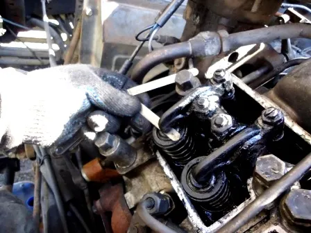
Hold the screw with a screwdriver, tighten the nut and check the clearance.
The 0.25 mm thick inlet valve and 0.35 mm exhaust valve should pass freely, while the 0.30 mm thick inlet and 0.40 mm exhaust valve must be pushed through.
Further clearance adjustment in the valve mechanism should be done in pairs in the cylinders:
- - 4th and 2nd (II position);
- - 6th and 3rd (III position);
- - 7th and 8th (IV position), turning the crankshaft in the direction of rotation each time by 180 degrees;
- - start the engine and listen to its work. With properly adjusted clearances, there should be no knocking in the valve mechanism;
- - install the clutch housing manhole cover and cylinder head covers.


