With a disconnecting valve, if necessary, the pneumatic line connecting the tractor vehicle with the trailer (semi-trailer) is blocked.
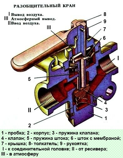
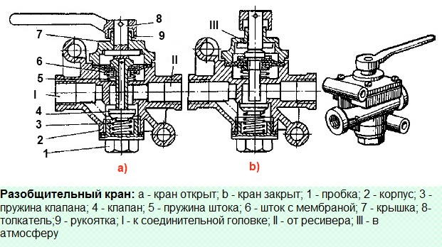
The disconnecting valve (Fig. 1) is designed to shut off, if necessary, the pneumatic line connecting the tractor vehicle with the trailer (semi-trailer).

There are three uncoupling valves on KamAZ tractors:
- on flatbed tractors - on the drawbeam in front of the coupling heads,
- on truck tractors - behind the cab on the right on a special bracket in front of the connecting flexible hoses.
Each faucet is attached with two bolts.
The trailer brake control line is connected to terminal II, compressed air is supplied to it through terminal 1.
If the handle 9 is located along the axis of the valve, the pusher 8 together with the stem 6 are in the lower position and the valve 4 is open.
Compressed air from outlet I through an open valve and outlet II flows from the tractor to the trailer (semi-trailer).

When the handle 9 is turned 90º, the stem 6 together with the membrane rises under the action of the spring 5 and air pressure.
Valve 4 sits on the seat in body 2, separating terminals I and II.
The stroke of the stem 6, determined by the screw profile of the cover 7, is greater than the stroke of the valve 4.
Stem 6 departs from the valve, compressed air from the connecting line through outlet II, axial and radial holes in stem 6 escapes into the atmosphere through outlet III in cover 7.
The coupling heads can then be disengaged.
Repair of the uncoupling tap
To do the job, you need tools: a bench, a vice, soft sponges, pliers, a hammer, a beard, a screwdriver, a 14x17 wrench, socket wrenches 14x17, 19x22, dishes for fuel and grease, a hair brush, a brush
Dismantling the Disconnect Tap
Install the uncoupling valve in a vise

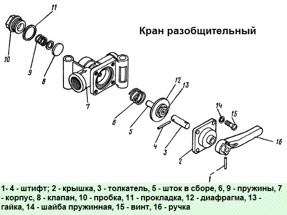
Remove pins 1 from the pusher 3 and remove the handle 16 of the crane
We unscrew the screws 15 for fastening the cover with washers 14 and remove the cover 2 from the body 7
Remove pusher 3 from cover 2
We remove the rod 5 with the membrane assembly and the spring 6 of the rod from the body 7
Unscrew the membrane fastening nut and disconnect it from the stem 5
We reinstall, the crane is in a vice and with a 19 socket wrench we unscrew the plug 10
Remove valve 8 with spring 9 from the body
Remove the body 7 of the crane from the vise
We wash the parts of the crane in diesel fuel, blow it with compressed air and check the technical condition
Assembling the Disconnect Tap
Install the valve body in a vise
We install valve 8 with spring 9 in the body 7 of the tap and screw in the plug 10
Reinstalling the crane in a vise
Install the membrane on stem 5 and tighten the membrane fastening nut
Installing the stem 5 with the membrane and the spring 6 of the stem into the valve body 7
Note. We cover the working surface of the rod with Ciatim-221 lubricant
We install pusher 3 in the cover 2
Note. We lubricate the working surface of the pusher with Ciatim-221
We install the cover 2 on the body 7 and screw in the screws 15 that fasten the cover to the body with washers 14
We put handle 16 on the pusher 3 of the crane and install pins 1 and 4 in the pusher
We test the uncoupling valve for operability and tightness
Test order:
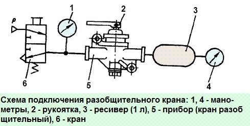
Connect the faucet according to the scheme

When the tap 6 is open and the device 5 is closed, air leakage from the device is not allowed
Turn on the device 5, turn the handle 2 by 90º until it stops.
The handle should move easily, without jamming. Air leakage is not allowed
Turn off the device 5, while the pressure (see Manometer 4) in the receiver 3 should drop to zero


