KAMAZ gearbox switching mechanism
The gear shift mechanism (Fig. a) is assembled in the top cover 2 of the gearbox housing and consists of three gear shift rods, gear shift forks 3, 5, 6, a locking mechanism, three rod position clamps,
fuse for engaging first gear and reverse gear, lever 20 (see Fig. 1) and rod.
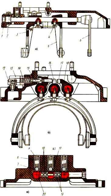
Gear shift mechanism: 1 - plug; 2 - gearbox cover; 3 - shift fork for fourth and fifth gears; 4 - set screw; 5 - fork for shifting second and third gears; 6 - fork for shifting first gear and reverse gear; 7, 10, 19 - balls; 8, 14 - springs; 9 - glass; 11 - pin; 12 - gearbox breather; 13 - spring cup for first gear and reverse fuse; 15 - fuse pusher; 16 - fork rod head; 17 - rod for shifting second and third gears; 18 - rod for shifting fourth and fifth gears; 20 - rod for shifting first gear and reverse
Inside the cover there are lugs for the passage of the rods, and in the front part there are three vertical holes for installing rod clamps and one horizontal hole for mounting the balls of the locking mechanism.
In the front part of the cover on the right there is breather 12 (Fig. 1 b) of the gearbox.
To protect against accidental engagement of first gear and reverse gear, there is an upper horizontal hole on the front right that has two diameters.
The fuse pusher 15 and the fuse are installed in the small diameter hole.
The large diameter hole has a thread for securing the glass 13.
A spring 14 is installed in the blind hole of the glass.
Each rod is designed to engage two gears: rod 18 for fourth and fifth gears, rod 17 for second and third gears, rod 20 for first gear and reverse gear.
To fix the rods, there are three holes on each of them, into which balls 7 enter under the action of springs (Fig. 1c).
To prevent the simultaneous engagement of two gears, a locking device is designed, consisting of a pin 11 and two pairs of balls 10, 19.
The balls are located between the rods in the bushings, the pin is located in the hole in the middle rod between the balls.
The diameters of the balls and the distance between the rods are chosen so that when any rod moves from the middle position, the balls come out of the holes of the moving rod and enter the holes of the stationary rods, blocking them with the body.
On each rod there are forks for shifting the corresponding gears.
The forks are fixed to the rods with set screws, which are secured with cotter wire.
The fork for shifting first gear and reverse gear has machined tabs with which it fits into the groove of the carriage for shifting first gear and reverse gear.
At the ends of the second and third gear shift fork there are holes into which crackers are installed; the cracks fit into the groove of the synchronizer carriage for shifting the second and third gears.
The ends of the fourth and fifth gear shift fork end in a machined surface with grooves.
The grooves of the fork include a ring for the synchronizer for shifting the fourth and fifth gears.
To move the rods and engage the required gear, rod heads are installed on the rod of the first gear and reverse gear and on the rod of the second and third gears, fixed with set screws; The shift fork for fourth and fifth gears is made integral with the head.
In the heads of the rods and in the head of the shift fork for fourth and fifth gears there are grooves that coincide in the neutral position and ensure unhindered swing of the lever in the transverse plane relative to the axes of the rods.
In the neutral position of the gearbox shift lever, lever 20 (Fig. 2) is in the middle position and its tab fits into the groove of the head of the second and third gear shift rod.
When the gear shift lever is moved from the neutral position to the right and left, the lever 20 rotates relative to the axis of the rod and enters the groove of the rod head of the first gear and the rear input gear.
When the gear shift lever 4 is moved forward or backward, the rod 19 moves, which, in turn, moves the lever 20.
Lever 20 moves the rod of the gear shift mechanism in the groove of the head of which it is located.
To prevent accidental engagement of the primary gear and reverse gear, a fuse pusher 25 is installed in the hole of the head 23 of the fork rod of the first gear and reverse gear, which under the action of fuse 24 and the spring constantly rests against lever 20 when it is in the neutral position.
Fuse 24 fits into the hole in the head and prevents it from moving in the longitudinal direction.
When engaging first gear or reverse gear, the lever 20, turning, acts on the fuse pusher 25, which, in turn, moves the fuse 24, compressing the spring and disengaging it from the head 23.
Lever 20 has a split head and is mounted on rod 19 using a key and tightened with a coupling bolt.
The rod 19 ends on the outer side with a flange intended for connection with the flange 18 of the rod 17 of the remote drive. The rod moves in a spherical support.
On the right side of the support, a set screw 21 is screwed in, which secures the lever 20 in the neutral position during adjustment work.
In the working position, the screw must be screwed in 21 mm and locked with nut 22.
The remote drive for controlling the gear shift mechanism consists of a swing lever 4 gear shift, lever support 2, front 10 and intermediate 17 rods with an adjusting flange 18.
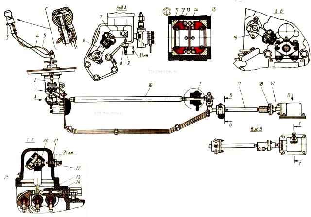
Lever support 2 is mounted on four bolts on the front end of the engine block.
A set screw 9 is screwed into the body of support 2 from below, locked with a lock nut 8.
Screw 9 is designed for proper installation and adjustment of the gear shift control drive.
In the working position, the screw should be turned out 31 mm and locked.
The front link 10 is installed on two spherical supports in the engine camber along the left row of cylinders.
The front traction support is located in the gear shift lever support, the rear one is located in the flywheel housing.
The support cavities are filled with lubricant.
The front and rear supports are structurally identical and each consist of two bushings 13 with internal sealing rings 12, two cotters and a spacer spring 14.
The front and rear parts of the rod end in cylindrical journals, on which are mounted on segment keys: in front - lever 7 of the tip, in the back - lever 16 with a ball head for connection with the cylindrical hole of the intermediate rod lever.
The intermediate rod 17 is made integral with the lever, the cylindrical bore of which includes the ball head of the lever 16.
An adjusting flange 18 is screwed onto the threaded part of the rod, with the help of which the rod is connected to the rod flange 19 with four bolts.
The rod assembly is mounted on two spherical supports: one rod support is located on the clutch housing, the other on the gearbox.
The spherical traction support is structurally identical to the front traction supports, their elements are interchangeable.
")

")
")
")
")
")
")
")