The control and measuring instrument system (Fig. 1) is designed to monitor the operating mode of units and individual assembly units of the vehicle, as well as to determine the speed of movement
The control and measuring instruments consist of indicators and sensors. All the indicators are installed on the instrument panel in the driver's cabin, the sensors are located on the chassis and engine units.
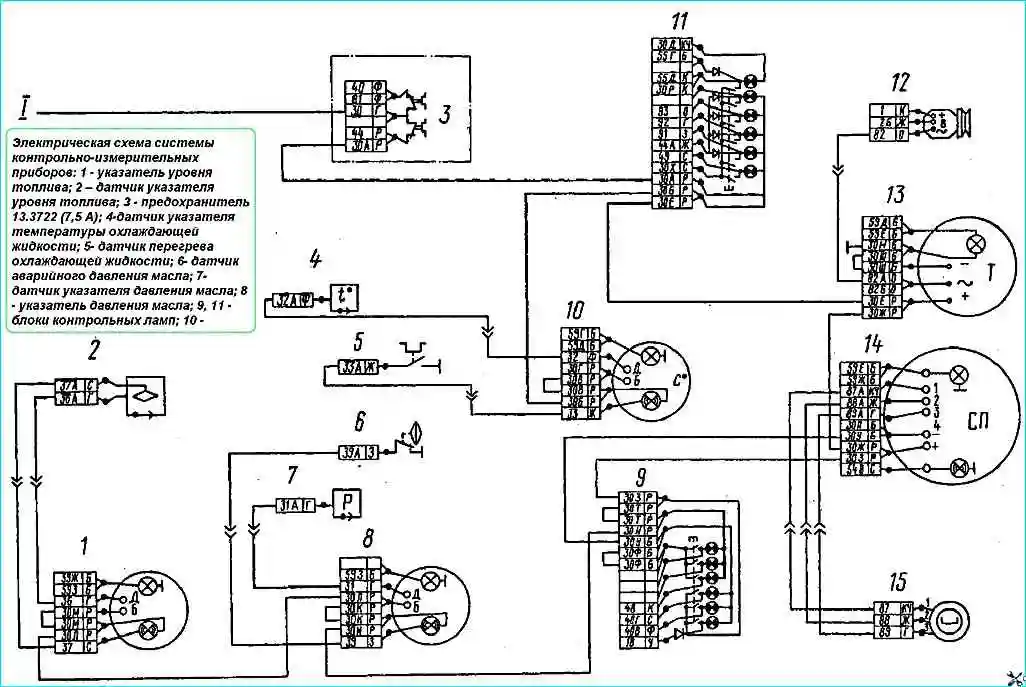
Electrical diagram of the instrumentation system: 1 - fuel gauge; 2 - fuel gauge sensor; 3 - fuse 13.3722 (7.5 A); 4 - coolant temperature gauge sensor; 5 - coolant overheating sensor; 6 - oil pressure emergency sensor; 7 – oil pressure indicator sensor; 8 – oil pressure indicator; 9, 11 – control lamp units
The electrical connection of the instruments is made using a single-wire circuit.
The negative terminal is the instrument panel, connected to the general ground of the vehicle; the devices are connected to each other in parallel via the instrument switch and the starter.

The functional diagram of the control and measuring devices has a version for vehicles with two fuel tanks. This version is shown in Figure 2.
")

")
")
")
")
")
")
")