The power supply system (Fig. 1) serves to power consumers when the engine is running
The sources of electricity are two batteries 6 connected in series, a generator 2 connected in parallel to the batteries.
The negative terminal of the batteries is connected to the vehicle body through a remote-controlled ground switch 7.
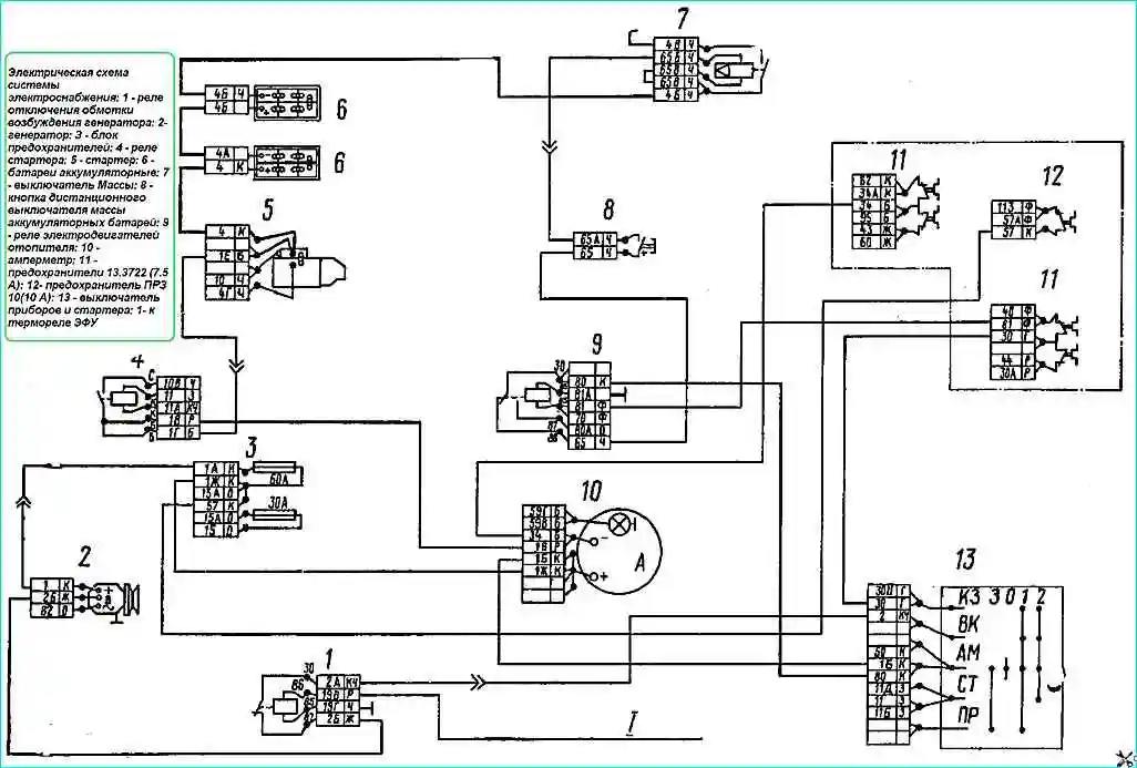
The circuit is equipped with relay 1, which breaks the excitation winding circuit of the generator when the electric fuel pump is operating.
In addition, when the key of switch 13 of the instruments and starter is in the working position, current is not supplied to button 8 of the remote mass switch, which prevents accidental disconnection of the mass when the engine is running (disconnection of the batteries is possible only after disconnecting the generator from the electrical system by setting the key of the switch of the instruments and starter to the neutral position).
Below are the electrical circuits of these systems and their description.
On the circuits, next to the symbolic image of the elements of electrical equipment, the numbers of the connected wires are given, their colors are indicated by letters: B - white; G - blue; Zh - yellow; Z - green; K - red; KCh - brown; O - orange; R - pink; S - gray; F - violet; Ч — black.
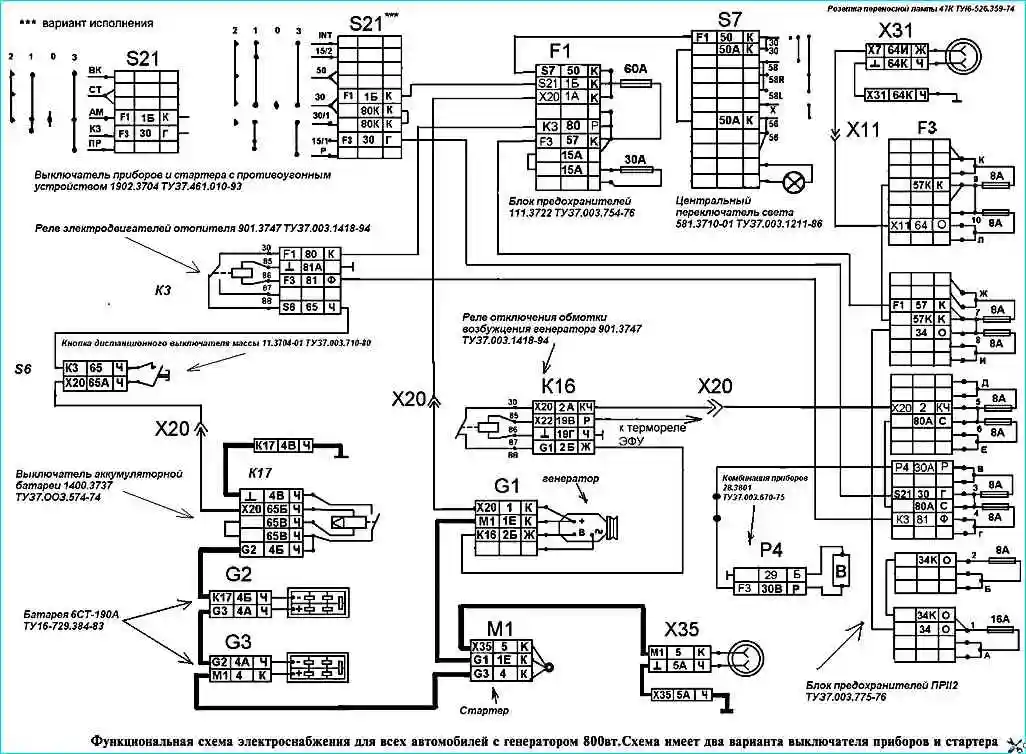
Fig. 2. Functional diagram of the power supply for cars with an 800 W generator. The diagram has two options for switching off the devices and the starter
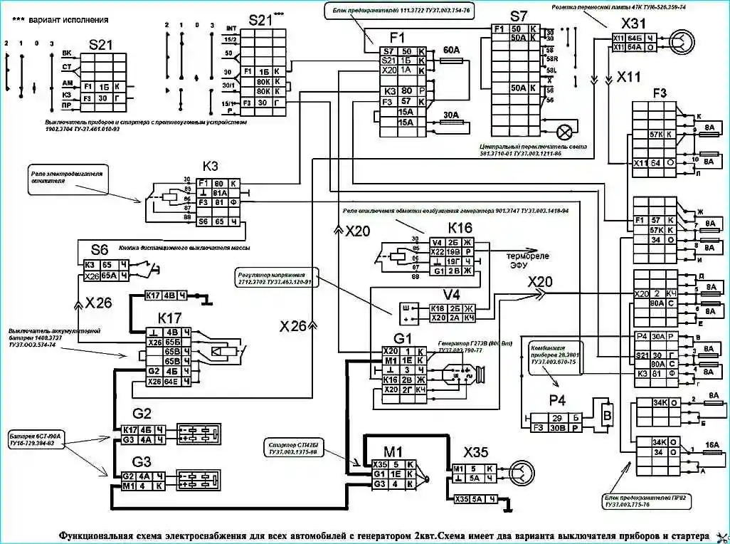
Fig. 3. Functional diagram of the power supply for cars with a 2 kW generator. The diagram has two options for switching off the devices and the starter