Design and operation of Kamaz auxiliary brake devices
The auxiliary brake (sometimes called the engine retarder brake) serves to reduce the load and temperature of the service brake brake mechanisms.
When the retarder is applied, the engine exhaust pipes are closed and the fuel supply is cut off.
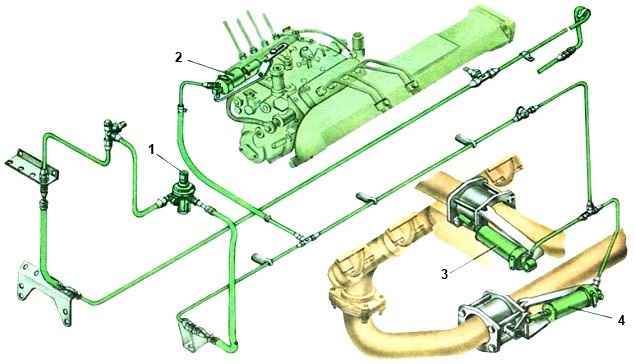
The drive circuit for the auxiliary brake and other consumers consists of a part of a double safety valve, a pneumatic valve, two pneumatic cylinders and a pneumatic cylinder for the stop lever drive, a pneumatic-electric sensor, pipelines and hoses between these devices.
Air enters the circuit from a condensing receiver and two circuits.
In the exhaust pipes of the muffler there is a housing and a damper mounted on the shaft.
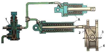
A rotary lever connected to the pneumatic cylinder rod is also attached to the damper shaft.
The lever and the associated flap have two positions. The internal cavity of the body is spherical.
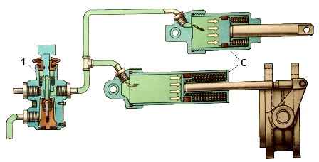
When the auxiliary brake system is turned off, the damper is installed along the flow of exhaust gases, and when turned on, it is perpendicular to the flow, creating a certain back pressure in the exhaust manifolds.
At the same time, the fuel supply is stopped. The engine starts operating in compressor mode.
From the auxiliary brake drive circuit, compressed air is supplied to additional (not the brake system) consumers: pneumatic signal, pneumatic-hydraulic clutch booster, etc.
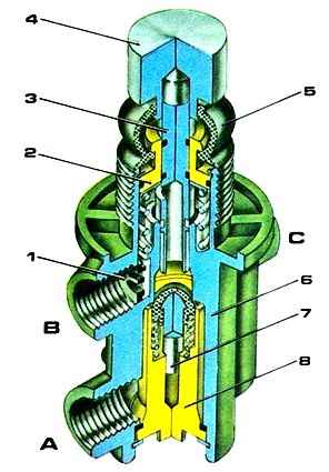
The design and operation of the safety valve are discussed above.
Pneumatic cylinders operate the engine retarder mechanisms.
For TO-1, remove the auxiliary brake system mechanisms, clean their internal surfaces from carbon deposits, wash in kerosene, blow with compressed air and reinstall;
Possible malfunctions of the auxiliary brake system and methods of elimination
Cause of malfunction - Remedy:
There is no braking of the road train when the auxiliary brake system is turned on
Malfunction of the pneumatic valve for turning on the auxiliary brake system, the pneumatic cylinders of the auxiliary brake system flap drive, the fuel supply cylinder, the damper mechanisms, the sensor for turning on the auxiliary brake system, the solenoid valve
- Replace faulty assembly units and parts.
If the cylinders are faulty, disconnect their rods and manually check the rotation of the valves. There should be no jams. If necessary, remove the auxiliary brake system assemblies, clean them of carbon deposits, wash them and dry them.
If necessary, replace the sensor and valve
Compressed air leak - Fix the leak
Clogged pipelines - Remove the pipelines and blow them out with compressed air
When the tractor is braked by the auxiliary braking system, the trailer (semi-trailer) does not brake
The pneumoelectric sensor for turning on the solenoid valve of the trailer (semi-trailer) brake system is faulty
- Replace the sensor
Failure of contact in the electrical connections of the tractor and trailer (semi-trailer) in the area from the sensor to the solenoid valve
- Find the location of unreliable contact and fix the problem
Electromagnetic circuit malfunction trailer (semi-trailer)
- Replace the valve
The air pressure supplied by the trailer (semi-trailer) solenoid valve to the brake chambers does not correspond to the norm: i.e. pressure less than 59 kPa (0.6 kgf/cm 2)
- Without removing the solenoid valve, adjust it with the screw screwed into the bottom of the valve body. When screwing in the screw, the air pressure passed through the valve increases, and when turning it out, it decreases.
Measure the air pressure with a pressure gauge connected to the control valve of the trailer axle or semi-trailer bogie
")

")
")
")
")
")
")
")