The master cylinder is mounted on the clutch pedal bracket.
In the housing 3 of the main cylinder there are cylindrical “A” and compensation “C” cavities in which the working fluid is located.
The case is covered with a protective cover.
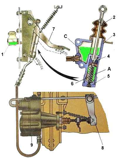
In the cylindrical cavity “A” there is a piston 4 with a sealing collar.
There is a hole in the piston that is closed during the working stroke by an o-ring located at the end of rod 2.
When the clutch pedal is released, piston 4 is in the upper position under the influence of spring 6 (see Fig. 1).
The cylindrical cavity “A” is closed from below with a plug, in the center of which there is a hole for connecting hydraulic drive pipelines.
When the clutch pedal is released, the cylindrical “A” and compensation “C” cavities communicate with each other through a hole in the piston and cuff, since there is a gap between the end of the rod 2 and the piston 4.
When you press the clutch pedal, the rod moves, closes the hole and separates cavities “A” and “C”.
As the pedal moves further, the liquid from the cylindrical cavity “A” is forced out by the piston through the hydraulic pipelines to the amplifier.
The normal liquid level in the tank should be 15-20 mm below the upper edge of the neck.
Bleeding the clutch hydraulic system
Perform bleeding of the clutch drive hydraulic system after eliminating leaks in the hydraulic drive in the following order:
- Clean the rubber protective cap of the air release valve from dust and dirt, remove it and put the rubber hose supplied with the car onto the valve head. Dip the free end of the hose into Neva brake fluid poured into a clean glass container.
- Press the clutch pedal sharply 3-4 times, and then, leaving the pedal pressed, unscrew the air release valve ¼-⅓ turn. Under the influence of pressure, part of the liquid and the air contained in it in the form of bubbles will come out through the hose.
- When the liquid stops coming out, close the air release valve.
- Repeat operations according to paragraphs. 2 and 3 until the release of air from the hose completely stops.
During the bleeding process, it is necessary to add brake fluid to the system, not allowing its level in the compensation tank of the master cylinder to decrease by more than ⅔ from normal in order to avoid atmospheric air entering the system.
After completing the bleeding, with the clutch pedal pressed, screw the air release valve all the way and only then remove the hose from its head and put on the protective cap.
Next, set the normal fluid level in the master cylinder.
Brake fluid that is released from the hydraulic system during bleeding can be used again after settling and subsequent filtration.
The quality of pumping is determined by the full stroke of the pneumatic hydraulic booster pusher.
Check for condensation in the power cylinder of the air-hydraulic booster.
To drain the condensate, unscrew the plug in the aluminum housing of the air-hydraulic booster.
To drain completely, lightly press the clutch pedal.
At least once every three years, it is recommended to flush the clutch drive hydraulic system with technical alcohol or clean brake fluid, disassemble the master cylinder and pneumatic power steering and refill with fresh brake fluid.
Wash the hydraulic system pipelines with alcohol or brake fluid and blow them with compressed air, having first disconnected both ends. Before assembling, moisten the pistons and cuffs of the hydraulic system with brake fluid.
Replace defective (hardened, damaged working edges and worn) cuffs and protective covers.