Maintenance of brake mechanisms and brake pneumatic drive Kamaz
Maintenance of brake mechanisms consists of lubricating the adjusting levers and bushings of the expansion cam shafts;
- - in regulating the strokes of the brake chamber rods and securing the brake chambers and their brackets;
- - in checking the condition of brake drums, pads, linings, tension springs and expansion knuckles (with the hubs removed).
The adjusting levers of the brake mechanisms are lubricated through grease nipples until fresh grease is squeezed out.
The expansion cam shaft bushings are also lubricated through grease nipples, but it should be borne in mind that the amount of lubricant should be moderate (no more than five strokes when lubricating with a manual syringe), since excess lubricant can get into the brake mechanism.
The stroke of the brake chamber rods is adjusted with cold brake drums and nominal air pressure in the brake pneumatic drive.
The parking brake must be released. The work is performed by two performers, one of whom must be in the vehicle cabin.
Measure the stroke of the rods with a ruler, placing it parallel to the rod and resting its end against the brake chamber body. Mark the location of the extreme point of the rod on the ruler scale, press the brake pedal all the way and again mark the location of the same point of the rod on the scale.
The difference in the results obtained gives the value of the rod stroke.
If the rod stroke exceeds 40 mm, it is necessary to loosen the locking bolt and, by rotating the worm axis of the adjusting lever, move the shoes apart until they come into contact with the brake drum, i.e., you need to rotate the worm axis until it stops.
After this, you should bring the pads together by turning the worm axis half a turn in the opposite direction (2-3 clicks of the lock), thereby ensuring the smallest stroke of the rods, which should be equal to 20 mm for KamAZ-4310, -43105, -5320, -5410 and -55102: for KamAZ-5511, -53212 and -54112 vehicles it is 25 mm on the intermediate and rear axles and 20 mm on the front.
You need to make sure that when turning the compressed air supply on and off, the brake chamber rods move quickly, without jamming.
Check the rotation of the reels. They should rotate freely without jamming, without touching the pads.
It is necessary that the rods of the right and left chambers on each axle have as equal a stroke as possible (the permissible difference is no more than 2...3 mm) to obtain the same braking efficiency of the right and left wheels.
After checking that the adjustment is correct, tighten the adjusting lever lock bolt.
Inspection of the brake mechanisms reveals the need to replace some parts. At the same time, it is taken into account that wear of the working surface of the brake drum is allowed no more than 1 mm; chips, cracks, and chipping of brake friction linings are unacceptable; their wear must correspond to the value at which at least 0.5 mm remains to the rivet heads.
If you need to replace one of the left or right brake linings, change all the linings on both brake mechanisms (left and right wheels).
After replacing the brake linings, the brake mechanism is fully adjusted.
To do this, loosen the nuts securing the shoe axes and bring the eccentrics closer together, turning the axes of the shoes so that they are positioned towards each other with the beveled sides of their outer ends, then by turning the axis of the worm of the adjusting lever, press the brake shoes to the drum, after that, turning the eccentric axes in one side or the other, install the pads, ensuring they fit snugly to the drum.
The fit of the pads is checked with a 0.1 mm thick feeler gauge, which should not pass anywhere along the entire width of the pad. With this position of the pads, tighten the axle nuts and set the minimum stroke of the brake chamber rod.
After the specified adjustment, the following gaps are achieved between the brake drum and the pads: at the expanding fist - 0.4 mm, at the axles of the pads - 0.2 mm.
The brake pedal travel must be at least 100-130 mm, of which 20-30 mm is free play.
When fully pressed, the pedal should not reach the cabin floor by 10...30 mm. The pedal stroke is measured with a ruler at a distance of 210-220 mm from the axis of rotation.
The end of free play is taken to be the moment the start of extension of the brake chamber rods or the moment the brake lights come on.
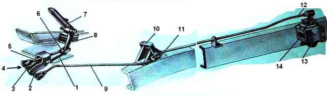
If necessary, adjust the pedal stroke by changing the length of the rod 6 (see Fig. 1) with the adjusting fork 5.
At full pedal travel, the brake valve lever should be 31.1-39.1 mm.
Daily maintenance of the brake drive involves a small number of operations to ensure trouble-free operation.
This is mainly control and diagnostic work that does not require the use of instruments; they are performed by the driver when preparing the car for departure and during work on the line;
To check the serviceability of the control dumps on the instrument panel, press the test button, and all control lamps should light up; they turn on even when the pressure in the receivers is less than 480-520 kPa.
To check the operability of the drive, you should activate the vehicle brake controls: press the brake pedal, turn on and off the parking brake, press the auxiliary brake valve button, release the energy accumulators with the emergency brake release button.
Every day at the end of the working day, condensate is drained from the receivers.
At an air temperature of -(- 5 °C) and below, pour (once a week or after a run of 1000 km) a fresh portion of ethyl alcohol into the antifreeze guard. Before adding alcohol, it is necessary to drain the condensate from the fuse.
When connecting the trailer, check that the connection heads are connected correctly and that the disconnect valves are open.
When servicing the pneumatic drive of the car brakes, you must also make sure that it is tight. Particular attention should be paid to the tightness of connections of pipelines and flexible hoses, since this is where air leaks most often occur.
Lots of strong air leakage are determined by ear, and weak ones - using a soap emulsion.
Air leaks from the connections of the brake system pipelines are eliminated by tightening them and leaking pipelines and flexible hoses are replaced.
Check the cotter pins of the brake chamber rods and the pins of the two-section crane drive. The protective covers of the brake chambers and brake valve must not be damaged.
During the second maintenance, the operability of the pneumatic brake drive is checked using the control outlet valves using pressure gauges.
Check the tightness of the nuts securing the compressor to the engine and the tightness of the nuts securing the compressor cylinder head.
Tightening is done evenly in a cross pattern in two steps. Check the fastening of the brake chamber clamps, the fastening of the brake chamber brackets and the chambers themselves to the brackets.
Particular attention should be paid to the fastening of energy accumulators. Play in their fastening is unacceptable, as this leads to separation of the device from the bracket.
By compressor
During seasonal maintenance, the compressor head must be removed to clean the pistons, valves and seats. Compressor valves that do not provide tightness must be ground into seats or replaced.
In the pressure regulator, it is necessary to wash or replace the filter element, which is located under the bottom cover.
You need to be careful when screwing in the cover, since the thread is conical and distortions when installing it are unacceptable. They lead to thread failure, which is then impossible to restore.
Before installation, it is recommended to lubricate the thread with graphite lubricant to prevent it from “sticking.”
As the compressor operates, the cylinder-piston group wears out and the valve tightness is compromised.
In case of these malfunctions, the filling time of the pneumatic system (before the warning lights are extinguished) at a crankshaft speed of 2200 rpm exceeds the setting 8 minutes or the compressor does not develop the specified pressure at all (700-750 kPa).
In addition, wear of the cylinder-piston group leads to oil being sucked into the pneumatic system.
After filling the pneumatic system with air, the unloading valve in the pressure regulator opens and the oil that entered the pneumatic system along with the air is thrown out and settles on the regulator and frame. This is an external sign of a compressor malfunction.
It should be noted that oil consumption through the compressor may increase due to clogging of the air cleaner.
As clogging occurs, the vacuum at the inlet increases and the compressor, even with a working piston group, sucks in oil mist from the crankcase and then throws it out into the pneumatic drive at the outlet.
Leaking of the compressor cylinder head gasket, internal cracks in the head or block lead to the fact that liquid from the cooling system is sucked into the cylinders, and then, together with air, goes into the pneumatic drive.
The coolant level in the expansion tank drops, and the liquid in it bubbles. This happens because the piston on the compression stroke pushes air into the compressor cooling jacket, and then The air and liquid are discharged into the expansion tank.
There is another dangerous consequenceof the considered malfunctions
The liquid that gets into the compressor cylinders seeps into the compressor crankcase through the gaps between the cylinder, piston and rings and flows from it into the engine oil sump. Therefore, when looking for where coolant gets into the oil, you must also keep in mind the compressor.
Brake malfunctions in most cases are caused by malfunctions of pneumatic drive devices.
The most likely malfunctions that can be detected and eliminated by a driver without the use of diagnostic equipment are discussed below
If the pneumatic drive receivers are not filled, and the pressure regulator vents air into the atmosphere, then there may be several reasons for this malfunction: the pipeline between the regulator and the safety valves is blocked; The pressure regulator is faulty - most often the filter element is clogged with oil or ice crystals (in winter).
If the receivers fill slowly and the pressure in them does not reach the nominal value (in the absence of leaks), then either the compressor or the pressure regulator is faulty.
If the receivers of a separate circuit are poorly filled, then first of all you should pay attention to the safety valve section of this circuit.
Ineffective braking of the vehicle by the service brake occurs if the drive is misaligned or the two-section brake valve is faulty.
If, when braking, the pressure in the brake chambers is nominal, then the brake mechanisms are misregulated or faulty.
If, when braking with the service brake, the pressure is below normal only in the brake chambers of the front axle, then either the lower section of the brake valve or the pressure limiter may be faulty.
If the pressure in the brake chambers is normal, and braking is ineffective, then the cause of this malfunction may be a large stroke of the brake chamber rods or, for example, oily brake pad linings.
If, when the brake pedal is pressed, the braking of the wheels of the rear trolley is ineffective or does not occur at all, while the front wheels brake normally, then the pneumatic part of the drive may have a malfunction in the upper section of the brake valve or the brake force regulator is faulty.
In this case, malfunctions in the adjustment of the brake mechanisms or the drive of the brake force regulator are possible.
If, after lowering the brake pedal, all the wheels of the car do not release the brakes, the two-section brake valve may be faulty (the pusher or the upper piston is jammed) or the brake valve drive may be misaligned (there is no free play of the pedal).
If, after releasing the brake pedal, air does not come out only from the rear brake chambers, then it is possible that the brake force regulator or the upper section of the brake valve is faulty.
These malfunctions lead to a delay in the release of air from the front brake chambers. If, when releasing the brakes, air is not released only from the front brake chambers, then the pressure limiter or the lower section of the brake valve is faulty.
The cause of air leaks through the atmospheric outlet of a two-section brake valve can be not only the sealing rings and valves in the valve itself, but also other devices of the brake system.
If leakage is observed when the pedal is released and the parking brake is on, then the brake valve is faulty.
Using a standard two-pointer pressure gauge, you can accurately determine which section of the valve is leaking: if the upper needle of the pressure gauge “falls” when the engine is not running, then the lower section of the valve is leaking; The lower arrow “falls” - the upper section is leaking.
If air leakage through the atmospheric outlet of the brake valve is observed only when the parking brake is released, and when it is turned on, it stops, then the trailer brake control valve with a two-wire drive or one of the energy accumulators is faulty.
You can determine a faulty device by supplying air to the energy accumulators from the emergency brake release circuit:
- if, when you press the emergency brake release button, the leak from the brake valve continues, then the pusher seal in the energy accumulator body is leaking, and if there is no leak, then the membrane in the trailer brake control valve is faulty.
If the wheels of the rear trolley do not release the brakes when the parking brake is turned off, then the cause of this malfunction may be the parking brake valve, accelerator or dual-line valve, and energy accumulators.
It is possible that one of the pipes in the parking brake circuit is clogged, frozen or pinched.
If one of the energy accumulators does not operate when moving the parking brake valve handle, then the cause may be dents on the body or sticking of the pusher. It is also possible that the pipeline through which air is supplied to the inoperative energy accumulator is blocked.
If the brake chamber rods come out when the energy accumulators are turned on, and the car does not brake effectively enough, then it is necessary to check the stroke of the rods and the serviceability of the brake mechanisms and wheels.
The most common malfunctions in the parking brake circuit, as well as in the entire pneumatic drive, are compressed air leaks due to damage to the sealing rings and cuffs.
Air leakage from under the parking brake valve handle when the brake is released is caused by a leaky rod seal in the guide.
The cause of air leakage from the atmospheric outlet of the parking brake valve is not always a leak in the seals in the valve itself.
For example, a leak may occur due to a malfunction of the two-wire trailer brake control valve.
To determine the faulty device, fill the pneumatic drive with compressed air, turn on the parking brake, and disconnect the control line tube from the tap.
If air leakage from the atmospheric outlet continues, then the parking brake valve is faulty; If a leak is observed from the disconnected tube, then the trailer brake control valve is faulty.
If air leaks from the atmospheric outlet of the accelerator valve during braking and when releasing the parking brake, then the sealing ring of the atmospheric outlet of the valve is leaking.
Air leakage through the atmospheric outlet of this device when braking with the parking brake is caused by the loss of tightness of the inlet valve, and when the brake is released, by the exhaust valve. In the latter case, the rear wheels are not released.
Sometimes an air leak through the accelerator valve is observed when the parking brake is on and the pedal is pressed at the same time.
In this case, one of the energy accumulators is faulty - air from the brake chamber enters the energy accumulator through the seal of the pusher pipe and then through the accelerator valve into the atmosphere.
During operation in energy accumulators, the seals of the piston in the cylinder and the pusher pipe in the housing wear out and fail.
When the parking brake is released, compressed air from under the piston flows through a leaky seal into the cavity above the piston and through the connecting hose on the side of the device under the brake chamber membrane, and from there into the atmosphere through the drain hole. In this case, when the parking brake is applied, the leakage stops.
If the seal of the pusher pipe in the energy accumulator body fails, then when the parking brake is applied, compressed air from under the piston enters the cavity above the membrane and escapes into the atmosphere through the brake force regulator.
If the regulator lever is in the upper position, then the air escapes to the atmosphere through the atmospheric outlet of the brake valve.
To detect a faulty energy accumulator, you need to release the parking brake and one by one disconnect the pipelines supplying compressed air to the rear brake chambers: for a faulty device, compressed air will come out of the cavity of the brake chamber.
If the emergency brake release button is pressed; the energy accumulators are not released (at a pressure in the pneumatic drive of more than 500 kPa), and after it is released, a small portion of compressed air comes out of the atmospheric outlet of the pneumatic valve, which means that the cross-section of the pipeline between the valve and the two-line valve is blocked. If, after releasing the button, there is no air coming out of the atmospheric outlet, then the valve itself is faulty.
If, when you press the tap button, air escapes into the atmosphere through the accelerator valve, then the dual-line valve is faulty.
Air leakage from the atmospheric outlet may occur due to a malfunction of both the tap itself and the two-line valve.
If an air leak is observed regardless of the position of the parking brake valve handle, then the valve itself is faulty.
But if the leak occurs only when the parking brake is released, and stops when braking, then the dual-line valve is leaking
In both cases, it is forbidden to plug the atmospheric outlet in the emergency brake release valve with a plug, since in this case spontaneous release of the parking brake is observed and the car’s spare brake does not work satisfactorily.
This is explained by this. that when you apply the emergency or parking brake by turning the parking brake valve handle, releasing air from the energy accumulators will be difficult or impossible.
If, when you press the auxiliary brake valve button, the engine does not stop (the flaps in the exhaust pipes do not turn) and the trailer does not brake, then there may be several reasons explaining this phenomenon: air is not supplied to the auxiliary brake valve, the pipeline is pinched or clogged , going from the tap to the pneumatic cylinders, the tap itself is faulty. The malfunction is determined by sequential shutdown of the pipelines.
If, when the auxiliary If the fuel is not turned off when the exhaust brake is applied, and the dampers in the exhaust pipes are activated, you should check whether compressed air is supplied to the pneumatic cylinder on the fuel pump. A malfunction may also occur in the mounting of the pneumatic cylinder.
The damper mechanism and the pneumatic cylinders that control them operate under the most unfavorable conditions.
That's why they fail more often than others, and dampers jam most often. If this happens with both dampers, the engine will not start; if with one, the engine starts, but smokes and does not develop power.
Pneumatic cylinders of the damper drive may also experience problems, the most common of which is loss of tightness of the piston cuff.
The trailer solenoid valve activation sensor is located on the left frame side member inside, next to the clutch housing.
If the sensor or electrical wiring fails and when the auxiliary brake is turned on, the trailer does not brake, and the road train may skid and fold.
If, after releasing the auxiliary brake valve button, the air from the pneumatic cylinders and the sensor is not released, i.e., the auxiliary brake does not turn off, then you need to check the atmospheric outlet in the valve.
In winter, it often freezes over, and a mud-ice plug forms in the atmospheric outlet, which prevents air from leaving the circuit.
If in this case the inlet valve in the auxiliary brake valve loses its seal, the brake will turn on spontaneously and the engine will stop for no apparent reason.
If there is no air in the auxiliary brake circuit, the engine can be started, but after a few minutes it spontaneously stops due to the supply of air through a faulty valve to the fuel shut-off pneumatic cylinder.
This faucet requires replacement. If there is no spontaneous engine stop, but it does not start after releasing the auxiliary brake valve button while the car is moving, then it is enough to clean the atmospheric outlet of the valve.