The transfer case used on all-terrain vehicles KamAZ-4310 and KamAZ-43105 serves to distribute torque between the front drive axle and the two drive axles of the rear bogie
When driving on an uneven road, it is necessary that the drive wheels of the front and two rear axles, when rolling around bumps that have different longitudinal profiles, can rotate at different speeds.
For example, when the front wheels roll over a protrusion (hillock) located on the path of the car, the speed of their rotation, compared to the rear wheels rolling at this time on a flat area, should increase, since the path traversed by the front wheels in this area road surface, more.
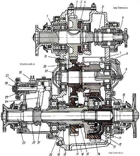
Transfer box of the KauA3-4310 car: 1 - input shaft with flange; 2 - drive gear; 3 - top hatch cover; 4 - power take-off gear; 5 - power take-off clutch (only on KamAZ-4310); 6 - power take-off (only on KamAZ-4310); 7 – oil sump; 8 - reduction gear; 9 - fitting; 10 - rear axle drive shaft; 11 - rear differential race; 12 - epicyclic (crown) differential gear; 13 - drive gear of the center differential; 14 - sun gear; 15 - front part of the differential housing; 16 - transfer case housing; 17 - overdrive gear; 18 - front cover of the transfer case; 19 - plug; 20 - high gear clutch; 21 - differential lock clutch; 22 - drive gear of the electric speedometer; 23 - front axle drive shaft; 24 - differential lock clutch fork; 25 - pneumatic chamber; 26 – rod; 27 - membrane; 28 - switch; 29 - intermediate shaft; 30 - low gear clutch; 31 - intermediate
When the rear wheels roll over this protrusion, their rotation speed should also increase.
If the front and rear wheels are rigidly connected to each other through transmission mechanisms, they will always be forced to rotate at the same speed, as a result of which increased tire wear and large power losses to overcome friction between the wheels and the road are inevitable.
The ability to rotate the wheels of the front and rear axles at different angular speeds is provided by the center differential used in the transfer case.
However, the use of a differential drive on slippery roads and wet soils with low traction can lead to a decrease and loss of vehicle patency.
To increase cross-country ability, cars are equipped with a differential locking device.
In the transfer case, the torque supplied to the drive wheels can change, i.e., the transfer case is at the same time an additional gearbox that increases the limits of the gear ratio in the transmission.
Engaging the lowest (first) gear in the 3rd gearbox and in the transfer case makes it possible for the vehicle to overcome high driving resistance.
Transfer box design
The transfer case is mounted on the frame and bolted to four rubber pads, made according to a three-shaft design.
Inside the crankcase, the input shaft 1 is located on bearings (Fig. 1) with drive gear 2 and power take-off gear 4.
In the upper part of the crankcase there is a hatch, closed with a cover 3, for installing a special power take-off box.
This box allows you to take power from the input shaft up to 44.1 kW (60 hp) while the car is moving.
It is turned on when the car stops. A single-speed gearbox 6 for power take-off for the winch is installed in the bore of the rear end of the crankcase.
The gearbox part also includes an intermediate shaft 29 with an intermediate gear 31 and a gear 8 for a reduction gear, a front axle drive shaft 23 with an overdrive gear 17, and a differential with a drive shaft 10 for the rear axles.
Gear 8 of the downshift and gear 17 of the overdrive are mounted on roller bearings with aluminum cages.
An asymmetrical cylindrical center differential is installed on the drive shaft of the rear (intermediate and rear) axles.
The differential consists of a sun gear 14, four satellites, an epicyclic (crown) gear 12, mounted in a split differential housing.
When the differential is unlocked, the torques between the front and rear drive axles are distributed in a ratio of 1:2, providing constant and uniform traction across all drive axles.
When driving in difficult road conditions, the differential must be locked. In this case, max. ideal traction capabilities of the car.
The position shown in the figure corresponds to the position in the transfer case with the differential unlocked.
Gear shifting in the transfer case is carried out by an electro-pneumatic system, consisting of a three-position switch 1 (Fig. 2) installed in the cabin, two electro-pneumatic valves 2 and 3, two membrane-type gear shift mechanisms 7 and 12, switch 8 installed on mechanism 7 , pneumatic lines 4.
When switch 1 is set to position 1, downshift is engaged. No compressed air is supplied to the switching mechanisms. The position of the shift clutches corresponds to that shown in the figure
When switch 1 is set to position II, overdrive is engaged. Electro-pneumatic valve 2 turns on.
Air from the pneumatic system is supplied to the gear selector mechanism 7, the membrane of which moves the rod 9 through the pressure spring 10 until the cup 5 stops in the protrusions of the mechanism body.
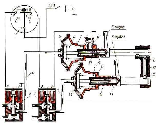
In this position, switch 8 is activated, which turns on electro-pneumatic valve 3.
Air enters the mechanism 12, the rod 15 of which moves through the pressure spring 14 until the glass 13 stops in the mechanism body. In this case, couplings 20 and 30 (see figure) move sequentially to the right.
The locking device, consisting of balls 16 (Fig. ) and pin 17, does not allow you to engage an upshift when the downshift is engaged.
When switch I is moved back to position I, return springs 6 and 11 sequentially, through a locking mechanism through pressure springs 10 and 14, return the mechanism rods until they stop in the covers.
When switch I is set to position H, neutral gear is engaged.
Only electro-pneumatic valve 2 is activated, as a result of which air is supplied to mechanism 7 and clutch 30 (see figure) moves to the right.
The vehicle can be equipped with a pneumatic transfer case control, which has a three-position cam valve 1 (Fig. 2), located in the cabin on the lower instrument panel to the left of the valve lever for engaging the center differential locking mechanism.
When the tap is switched from neutral position I to position II, a downshift is engaged, and an upshift in position III.
Switch 4 of the downshift indicator lamp 2 is located on the housing of the gear shift mechanism 3.
Installation of the warning lamp is provided in the left block of warning lamps of the instrument panel.
The center differential lock is also activated by a membrane pneumatic chamber, which differs from the gear shift chamber in the absence of a pressure spring.
The differential locking mechanism is activated by a pneumatic valve installed in the cabin under the instrument panel.
The transfer case is lubricated by splashing.
To supply oil to the bearings of the intermediate shaft reduction gears, the transfer case housing has an oil sump connected through holes in the crankcase, bearing cover, fitting, shaft with the bearing area
")

")
")
")
")
")
")
")