The pressure regulator automatically maintains the pressure in the pneumatic brake drive system within the range of 620-750 kPa, protects the pneumatic system from exceeding the maximum pressure (1000-1350 kPa) and protects the pneumatic system from contamination.
The pressure regulator (Fig. 1) is designed:
- - to regulate the pressure of compressed air in the pneumatic system;
- - protecting the pneumatic system from overload with excess pressure;
- - cleaning compressed air from moisture and oil;
- - ensuring tire inflation.
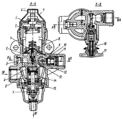
Compressed air from the compressor through output “IV” of the regulator, filter 2, channel 12 is supplied to the ring channel. Through check valve 11, compressed air flows to terminal “II” and then to the receivers of the vehicle’s pneumatic system.
At the same time, through channel 9, compressed air passes under the piston 8, which is loaded with a balancing spring 5.
In this case, the outlet valve 4, connecting the cavity above the unloading piston 14 with the atmosphere through terminal “I”, is open, and the inlet valve 13 is closed under the action of a spring.
Under the action of the spring, unloading valve 1 is also closed. In this state of the regulator, the system is filled with compressed air from the compressor.
When the pressure in the cavity under the piston 8 is equal to 686.5-735.5 kPa (7-7.5 kgf/cm 2), the piston, overcoming the force of the balancing spring 5, rises up, valve 4 closes, inlet valve 13 opens.
Under the influence of compressed air, the unloading piston 14 moves down, the unloading valve 1 opens, and the compressed air from the compressor through outlet “III” escapes into the atmosphere along with the condensate accumulated in the cavity.
In this case, the pressure in the annular channel drops and check valve 11 closes.

Thus, the compressor operates in unloaded mode without backpressure.
When the pressure in terminal “II” drops to 608-637.5 kPa (6.2-6.5 kgf/cm 2), piston 8 moves down under the action of spring 5, valve 13 closes
and outlet valve 4 opens. In this case, the unloading piston 14 rises upward under the action of the spring, valve 1 under the action
the spring closes and the compressor pumps compressed air into the pneumatic system.
Unloader valve 1 also serves as a safety valve. If the regulator does not operate at a pressure of 686.5-735.5 kPa (7-7.5 kgf/cm 2), then valve 1 opens, overcoming the resistance of its spring and the piston spring 14. Valve 1 opens at a pressure of 980.7-1274.9 kPa (10-13 kgf/cm 2). The opening pressure is adjusted by changing the number of shims installed under the valve spring.
For connecting special devices, the pressure regulator has a terminal that is connected to terminal “IV” through filter 2.
This outlet is closed with a screw plug 3. In addition, there is an air bleed valve for inflating tires, which is closed with a cap 17.
When screwing on the hose fitting for inflating tires, the valve is recessed, allowing access to compressed air into the hose and blocking the passage of compressed air into the brake system.
Before inflating the tires, the pressure in the receivers should be reduced to a pressure corresponding to the regulator activation pressure, since air cannot be taken out during idle.
")

")
")
")
")
")
")
")