Main gear of KamAZ vehicle
The main gear serves to increase torque on the drive wheels and transmit it from the driveshaft to the axle shafts at a right angle.
The constant increase in torque is characterized by the final drive ratio
The total gear ratio of the entire transmission is equal to the product of the gear ratios of the gearbox, transfer case and final drive and can be changed when different gears are engaged.
The total gear ratio shows how many times the speed of rotation of the drive wheels is reduced compared to the speed of the engine crankshaft.
The higher the gear ratio, the greater the traction force developed on the driving wheels of the car.
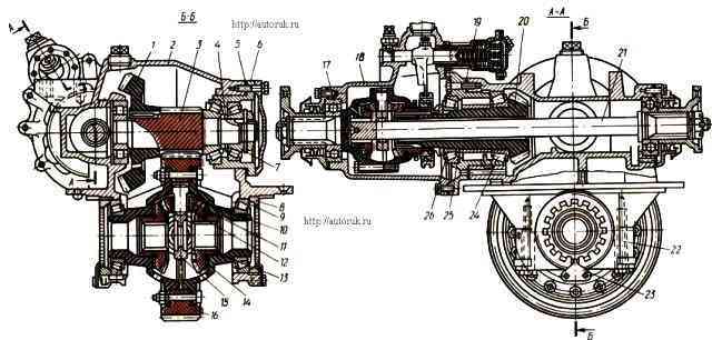
Main gear and differentials of the intermediate drive axle: 1 - driven bevel gear; 2 - main gear housing; 3 - drive cylindrical gear; 4, 14, 25 - adjusting washers; 5.19 - adjusting shims; 6 - cup of bearings; 7, 9, 24, 26 - tapered roller bearings; 8 - differential bearing adjusting nut; 10 - satellite support washer; 11 - satellite; 12 - satellite bushing; 13 - semi-axial gear; 15 - cross; 16 - driven cylindrical gear; 17 - ball bearing; 18 - center differential housing; 19 - gasket; 20 - drive bevel gear; 21 - drive shaft of the rear axle; 22 - bearing cover; 23 - stopper
Depending on the purpose of KamAZ vehicles, the bridge design provides four options for final drive ratios.
Gear ratios 7.22; 6.53; 5.94 are intended for vehicles operating as part of road trains, and the gear ratios are 6.53; 5.94 and 5.43 - for single cars.
KAMAZ vehicles use two-stage main gears, consisting of two gear pairs, a pair of bevel gears with helical teeth and a pair of cylindrical helical gears.
Changing the final drive gear ratio is achieved by installing spur gears with a different number of teeth.
When driving on an uneven road and when turning, the driving wheels of a car travel different distances in the same periods of time.
If the drive wheels were connected to each other by a common shaft, then in all cases of movement they would rotate with the same frequency, which would inevitably lead to slipping and slipping of the wheels relative to the road.
Slippage causes increased tire wear, increases power consumption, increases fuel consumption and makes turning difficult.
To avoid these disadvantages, drive axles are equipped with a differential, which allows the drive wheels to rotate at different frequencies relative to each other.
However, it should be taken into account that when driving on a slippery road, the presence of a differential contributes to the car skidding.
On KamAZ vehicles, a conical symmetrical cross-axle differential is used in each drive axle.
This means that the differential uses bevel gears and equal torques are transmitted to the right and left wheels.
On the intermediate drive axle of KamAZ vehicles with the wheel arrangement: 6X4, a center differential is also installed.
It allows the drive shafts of the main gears of the intermediate and rear axles to rotate at different frequencies, and therefore the wheels of these axles can also rotate at different frequencies.
The car's center differential is conical, symmetrical, lockable.
When the differential is not locked, it distributes torque between the main gears of the intermediate and rear drive axles almost equally.
Differential linkage ensures more uniform loading of drive parts to the drive wheels, reduces tire wear, and improves vehicle handling.
In difficult conditions and on slippery roads, the presence of a differential negatively affects the vehicle's maneuverability.
Under these conditions, it is blocked, the drive shafts of the main gears of the drive axles are rigidly connected and rotate at the same frequencies.
At the same time, slipping of the drive wheels is reduced, and the vehicle's cross-country ability is increased.
The main drive of the intermediate drive axle of vehicles with the 6X4 wheel formula is performed with passageway for driving the final drive of the rear axle.
The drive bevel gear 20 (Fig. 1) is installed in the neck of the main gear housing on two tapered roller bearings 24, 26, between the inner races of which there is a spacer sleeve and adjusting washers 25.
The splined end of the hub of this gear is connected to the bevel gear of the center differential, and inside the hub there is a drive shaft 21, one end connected to the bevel gear of the center differential, and the other, via a cardan transmission, to the drive shaft of the main transmission of the rear axle.
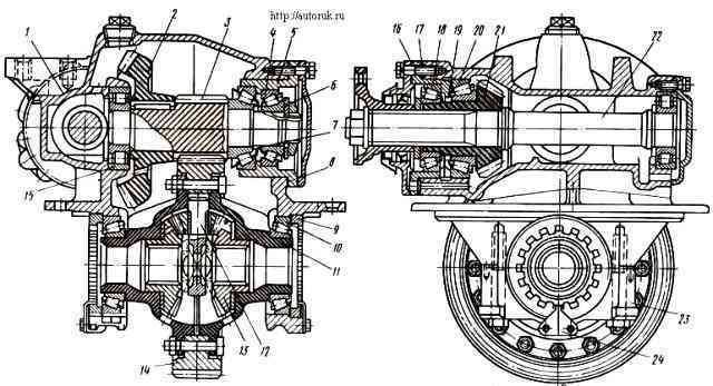
Main gear and differential of the rear drive axle: 1 - main gear housing; 2 - driven bevel gear; 3 - drive cylindrical gear; 4, 6, 10, 18, 20 - tapered roller bearings; 5 - cup of bearings; 7, 19 - adjusting washer; 8, 17 - adjusting shims; 9 - adjusting nut; 11 - differential cup; 12 - cross; 13 - semi-axial gear; 14 - driven cylindrical gear; 15 - roller bearing; 16 - gasket; 21 - drive bevel gear; 22 - rear axle drive shaft; 23 - differential bearing cover; 24 - stopper
The intermediate shaft rests at one end on two tapered roller bearings 7, between the inner races of which there are adjusting washers 4, and at the other end on a roller bearing installed in the bore of the main gear housing partition.
Tapered roller bearings 7 fix the intermediate shaft from displacement in the axial direction.
The drive cylindrical gear 3 with oblique teeth is integral with the intermediate shaft.
Driven bevel gear 1 is located at the end of the intermediate shaft and is kept from turning by a key.
The driving and driven bevel gears of the main gear are selected into sets at the factory, ground in and branded, indicating the serial number of the set.
The driven cylindrical gear 16, fixed in the cross-axle differential housing, rotates on tapered roller bearings 9. These bearings are adjusted with nuts 8.
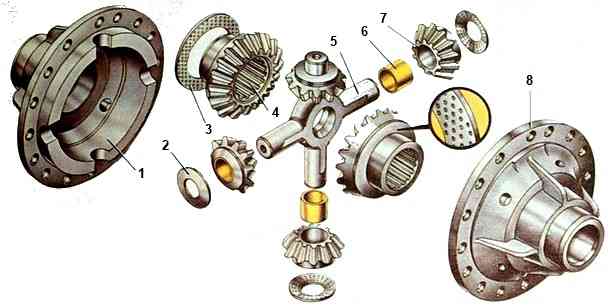
Between the halves (cups 1 and 8) of the differential housing (Fig. 2.) in the plane of the connector, a crosspiece 5 is clamped, on the spikes of which four bevel satellites 7 are freely mounted, each of which is meshed with two semi-axial gears 4, installed in differential housing.
All differential gears are spur-cut.
The ends of the satellites and their supporting surfaces in the differential housing are spherical, which ensures the necessary centering and correct engagement of the satellites with the axle gears.
To reduce friction and the likelihood of scuffing, floating support washers 3 and 2 are installed between the differential housing and the ends of gears 4 and satellites 7.
Washers are selected to a certain thickness when assembling the differential.
The drive wheel drive axles are connected to the corresponding side gears using splines.
Torque is transmitted from the center differential to the drive bevel gear 20 (see figure), then to the driven bevel gear 1, the driven spur gear 3 and the driven spur gear 16.
The torque from the cross-axle differential housing, to which the driven spur gear 16 of the main gear is attached, is transmitted to the crosspiece 15, and from it through the satellites to the axle gears.
Satellites 7 (Fig. 2), acting with equal force on the right and left gears of the axle shafts, create equal torques on them.
At the same time, due to insignificant internal friction, the equality of the moments is practically preserved both when the satellites are stationary and when they rotate.
Turning on the spikes of the crosspiece, the satellites provide the ability to rotate the right and left axle shafts, and therefore the wheels, at different frequencies.
The rubbing surfaces of the main gear and differential parts are lubricated by splashing the oil in the crankcase.
Lubricant enters the differential through windows in its housing, and to supply oil to the bevel bearings of the drive bevel gear and the intermediate shaft, longitudinal and radial channels are provided in the cups in which the bearings are installed.
The cavity of the main gear housing communicates with the atmosphere through the ventilation cap (breather).
The shafts are sealed by self-clamping cuffs protected by mud rings.
In the main gear of the rear axle, the drive bevel gear 21 (Fig. 3) differs from the similar gear of the intermediate axle in that its hub is shorter and has internal splines for connection with the drive shaft 22 of the rear main gear bridge.
Support tapered roller bearings 18 and 20 are interchangeable with the corresponding bearings of the intermediate drive axle.
The rear axle main drive shaft rests at its rear end on one roller bearing installed in the crankcase bore.
For lubricant circulation around the bearing, a channel is made in the crankcase neck. The end of the bearing is covered with a cover.
The remaining parts of the main drive and cross-axle differential of the intermediate and rear drive axles are similar in design.
")

")
")
")
")
")
")
")