The windshield cleaning system is designed to wash and clean windshields to ensure vehicle safety
It includes electric windshield wipers 27.5205 and windshield washers 1112.5208—01.
The electric windshield washer is controlled by a key switch and has an electric pump built into the washer reservoir.
The pump is powered through a 10A fuse.
The electric windshield wiper ensures that the blades operate in two modes and stop in their original position. It includes a gear motor, motorized brushes and a three-position switch.
The voltage to the gear motor is supplied through the heater motor relay, so the windshield wiper can be turned on when the instrument and starter switch is turned to position “1.”
The washer and wiper switches are located to the right of the steering column on the switch panel.
When the washer switch is turned on, current flows through the pump motor.
Current paths:
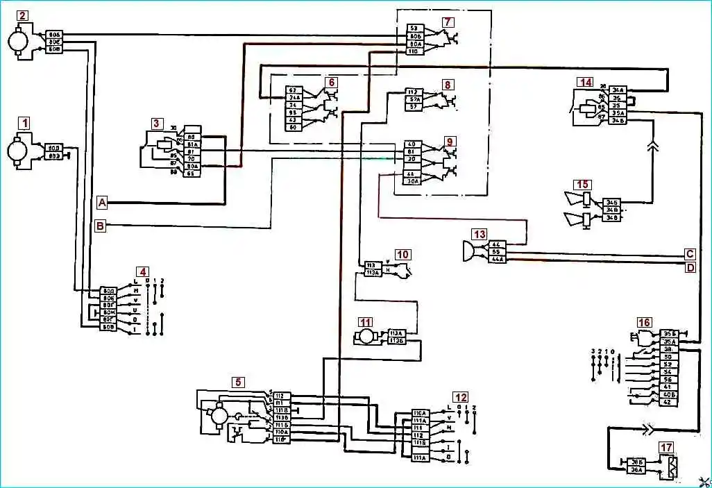
“+“ batteries, starter terminal, terminal B of the starter relay —► ammeter, terminal 1G connector, terminals 1G and 57 of the fuse block for current 60 and 30 A —► fuse for current 10 A —► open switch contacts —► washer motor —► housing —► “mass” switch — “—“ battery. The electric motor drives a pump, which supplies washer fluid through flexible tubes to two single-jet nozzles and then to the windshield.
The electric motor of the windshield wiper gearmotor has three brushes: one negative and two positive.
The negative blade is connected to the car body, and the positive blades are supplied with on-board voltage through the wiper switch.
When voltage is applied to different positive brushes, different rotation speeds of the electric motor armature and, accordingly, different operating modes of the windshield wiper blades are provided.
The design and replacement of a windshield wiper is described in the article - Design and replacement of a windshield wiper for a KAMAZ vehicle
The operating order of the windshield wiper is as follows:
- - when the instrument switch and starter are set to position “1”, the heater electric motor relay is activated, since voltage is supplied to its winding from the short-circuit terminal of the instrument switch and starter through a fuse for a current of 7.5 A;
- - when the relay is triggered, the voltage from its pin 30 is supplied to pin 87 and then through a 10 A current fuse to pin 110 of the gearmotor connector, gearmotor fuse, pin 110A of the gearmotor, pin 110A of the switch;
- - in position “1” of the windshield wiper switch, the voltage from its terminal 110A is supplied to terminal 111 and then to one of the positive brushes of the gear motor (top in the figure). At the same time, current begins to flow through the electric motor, since its negative brush (lower in the figure) is constantly connected to the car body; the electric motor through the gearbox and drive ensures the reciprocating movement of the brushes with a certain frequency;
- - when the windshield wiper switch is set to position “2”, the voltage from its terminal 110A is supplied to terminal 112 and then to the second positive blade (in the figure on the left); with this switch position, the windshield wiper operates more frequently;
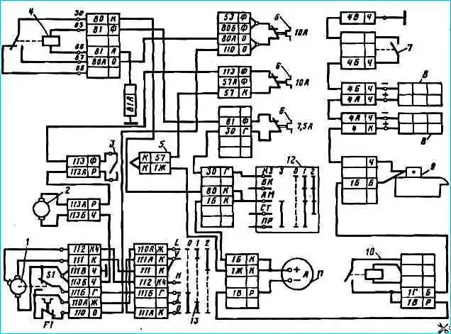
- - when the windshield wiper is turned off, the brushes return to their original position using the limit switch S1 of the gear motor. The state of the switch contacts (see Fig.2) shown for the initial state.
When the brushes move, the contacts switch to another position. Therefore, when the windshield wiper switch is set to the neutral position, the movement of the brushes continues to the original position, since in this case the voltage is supplied to the electric motor of the gear motor as follows;
- terminal 110 of the gear motor —► fuse F1 —► closed (lower) contacts of the limit switch —► terminals 111B of the gear motor and switch —► terminals 111 of the switch —► terminal 1114 of the switch —► terminals 111 of the switch and gear motor —► positive brush of the gear motor ( top).
When the wiper blades reach their original state (bottom of the windshield), the limit switch contacts return to their original state, open the power supply circuit of the gear motor and the wiper blades stop.
")

")
")
")
")
")
")
")