The following pre-heater failures may occur on a KamAZ vehicle:
- - the electric motor of the pump unit does not work;
- - the fuel in the preheater boiler does not ignite.
Signs of the first failure: in any operating position of the switch lever, the electric motor circuit does not turn on and the operation of the electric motor is not heard.
Reasons for refusal:
- - turn off the fuse;
- - switch failure; motor relay malfunction;
- - wire break between the relay and the electric motor;
- - electric motor malfunction.
Signs of the second failure: lack of a uniform hum of fuel combustion and heater heating.
Reasons for refusal:
- no spark charge occurs between the electrodes of the spark plug;
- The electric fuel heating relay, the electric fuel heater or the fuel solenoid valve is not working.
Checking the batteries, battery switch and connecting wires to the fuse in the pre-heater system circuit
The test is carried out using a test lamp by connecting it between the device being tested and the car body.
If the lamp does not light when you connect the lamp to the input terminal of the fuse, then you need to check the batteries.
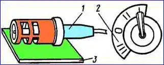
Checking the fuse for a current of 30 A

Press the safety button (Fig. 1),
Then connect the lamp to the fuse output terminal (Fig. 2).
In this case, the lamp should be on; if it does not light up, then the fuse is faulty
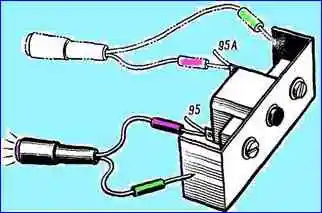
Checking the operating mode switch and connecting wires
Connect the test lamp to pin 96 (red wire) of the operating mode switch.
The lamp should be lit.
The serviceability of the switch is checked with a test lamp.
To do this, the end of one wire is connected to the car body, the end of the other wire is alternately connected to the terminals of the operating mode switch.
When connecting to a terminal with a green wire, the switch must be in position II, when checking terminals with blue wires - in position 1 or II, when checking a terminal with a brown wire - in position 1;
Checking the connecting wires from the switch to the motor contactor and the contactor itself

To check the serviceability of the wires, the test lamp is connected one by one to the contactor terminals (Fig. 3).
To check the serviceability of the electric motor contactor, it is necessary to connect a test lamp to contactor terminal 96 (white wire), and set the operating mode switch to position (III).
The lamp should be on, if it is not on, then the contactor is faulty;
Checking the electric motor of the pump unit and connecting wires to the contactor
The wire is checked by connecting a test lamp to the motor terminal. To check the operation of the electric motor, connect the “+” of the batteries to the terminal of the electric motor.
A healthy engine should be running.
A control ammeter connected in series with the electric motor measures the current consumed by the motor. It should not exceed 13-14 A.
At lower current levels, check the condition of the commutator and motor brushes.
If the current value is higher, the condition of the field winding and armature winding is additionally checked.
The check can also be done by placing the switch in position III and first checking the serviceability of the wire.
The control is carried out by ear: if the engine is running, then the wire is working.
However, electric motor failure can be caused not only by a malfunction in the electrical circuit, but also in the event of jamming of the fan impeller or liquid pump impeller attached to the armature shaft of the electric motor.
In this case, the armature will not rotate and the current in the electric motor circuit will be more than 30 A.
This will trigger the fuse and turn off the entire circuit electrically. their preheater devices.
Checking the electric fuel heater relay and connecting wires from the electric motor contactor
To check the operation of the relay, you must connect the wire from the test lamp to pin 100 (red wire) and move the switch to position III.
The lamp should be on; if it is not on, you must connect the test lamp to terminal 98A (black wire) with the same switch position.
If the lamp is on, then the relay is faulty, if it is not on, the wire is faulty;
Checking the electric fuel heater and connecting wires from the heater relay
The wire is checked by connecting a test lamp to the terminal of the electric heater (operating mode switch in position III).
The lamp should be on. The serviceability of the electric heater is checked by connecting a test lamp to its terminals.
The other wire from the lamp is connected to the battery.
The lamp will light if there is no fault in the electric heater circuit.
You can measure the resistance of the electric heater or the current consumed by the electric heater. It should not exceed 8.5 A;
Checking the ignition coil, transistor switch and connecting wires
The wire from the ignition coil to the operating mode switch is checked with a test lamp, the output of which is connected to terminal 99 of the ignition coil (operating mode switch in position II).
The lamp should be on.
To check the transistor switch and ignition coil, disconnect the high-voltage wire from the spark plug and bring its tip with a gap of 8-10 mm to the car body.
Set the operating mode switch handle to position II and observe sparking.
No spark is a sign of failure of the switch or ignition coil;
Checking the spark plug
The spark plug is unscrewed from the boiler, and then a high-voltage wire from the switch is connected to it and sparking between the electrodes is checked (Fig. 4);
Checking the wire from the operating mode switch to the solenoid fuel valve and the valve itself
When checking the valve, set the switch to position 1. At this moment, you should hear a click when the electromagnet is triggered.
")

")
")
")
")
")
")
")