Combined lubrication system with "wet" sump
The system includes an oil pump, an oil filter, a water-oil heat exchanger, an oil sump, an oil filler neck, an indicator tube and an oil level indicator.
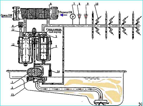
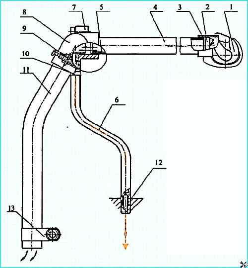
Lubrication system diagram: 1 - oil pump; 2 - valve; 3 - filter; 4 - bypass valve; 5 - partial-flow filter element; 6 - water-oil heat exchanger; 7, 8 and 9 - control devices; 10 - piston cooling nozzles; 11 - thermal valve; 12 - full-flow filter element; 13 - oil sump; 14 - safety valve
The lubrication system diagram is shown in Fig. 1
From the crankcase 13, the oil pump 1 supplies oil to the oil filter 3 and through the water-oil heat exchanger 6 to the main line, then to the consumers.
The lubrication system also includes the valve 2 of the system, which provides a pressure in the main oil line of 392-539 kPa (4.0-5.5 kgf/cm 2) at the rated speed of the engine crankshaft, the bypass valve 4, adjusted to operate at a pressure drop on the filter of 147-216 kPa (1.5-2.2 kgf/cm 2) and the thermal valve 11 for turning on the water-oil heat exchanger.
At an oil temperature below 95 °C, the valve is open and the main flow of oil enters the engine, bypassing the heat exchanger.
At an oil temperature of more than 110° C, the thermal valve is closed and the entire oil flow passes through the heat exchanger, where it is cooled with water.
This ensures rapid engine warm-up after starting and maintaining the optimal temperature during operation.
Structurally, the thermal valve is located in the oil filter housing.
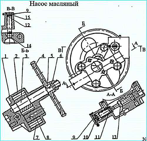
Oil pump: 1 - cover; 2 - housing; 3 - drive gear; 4 - driven gear; 5 - key; 6 - nut; 7 gear; 8 - axle; 9 - cotter pin; 10 plug; 11, 12 - springs; 13 - valve; 14 - ball; 15 - adjusting washers
The oil pump (see figure) is fixed to the lower plane of the cylinder block.
The driving gear is pressed onto the front end of the crankshaft and has 64 teeth, the driven gear has 52, i.e. the gear ratio is 0.8125.
The clearance in the engagement of the drive gears is adjusted by gaskets installed between the mating surfaces of the pump and the block, which should be 0.15-0.35 mm, the tightening torque of the bolts securing the oil pump to the block should be 49-68.6 Nm (5-7 kgf.m).
The oil pump is gear-type, single-section. Contains housing 2, cover 1 and gears.
The cover contains lubrication system valve 13, with spring 11. A safety valve consisting of a ball, spring and adjusting washers is installed in the discharge channel.
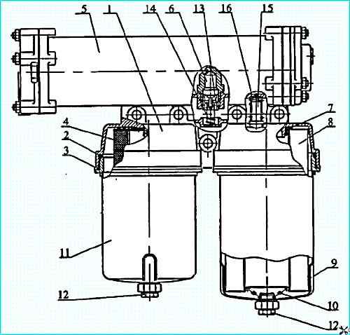
Oil filter with heat exchanger: 1 filter housing; 2, 3 - sealing rings; 4 - partial-flow filter element; 5 - heat exchanger; 6 - thermal force sensor; 7 - gasket; 8 - full-flow filter element; 9, 11 - caps; 12 - drain plug; 13 - thermal valve piston; 14 - thermal valve spring; 15 - bypass valve; 16 - bypass valve spring
The oil filter (see figure) is fixed on the right side of the cylinder block and consists of a housing 1, two caps 9 and 11, in which full-flow 8 and partial-flow 4 filter elements are installed.
The caps are screwed into the housing with a thread. The caps are sealed in the housing by rings 2 and 3.
The filter housing also contains a bypass valve 15 and a thermal valve for turning on the water-oil heat exchanger.
The oil cleaning in the filter is combined.
The main flow of oil passes through the full-flow filter element 8 before reaching consumers, the fineness of the oil cleaning from impurities is 40 μm.
Through the partial-flow filter element 4 passes 3-5 l/min, where impurities larger than 5 μm are removed.
The oil is drained from the partial-molasses element into the crankcase. With this scheme, a high degree of oil cleaning from impurities is achieved.
The oil sump is stamped, attached to the cylinder block through a rubber cork gasket. The tightening torque of the crankcase mounting bolts is 8 - 17.8 Nm (0.8 - 1.8 kgf.m).
The water-oil heat exchanger activation thermostatic valve consists of a spring-loaded piston 13 with a thermal force sensor 6.
At temperatures below 93 °C, piston 13 isI am in the upper position and the main part of the oil flow, bypassing the heat exchanger, enters the engine.
When the oil temperature reaches (95+2) °C washing the thermal power sensor 6, the active mass located in the cylinder begins to melt and, increasing in volume, moves the sensor rod and piston 13.
At the oil temperature of (110+2) °C, piston 13 separates the cavities in the filter before and after the heat exchanger and the entire oil flow goes through the heat exchanger.
When the oil temperature exceeds 115 °C, the temperature sensor is triggered and the signal lamp on the instrument panel lights up.
The water-oil heat exchanger (Fig. Oil filter with heat exchanger) is installed on the oil filter, shell-and-tube type, prefabricated.
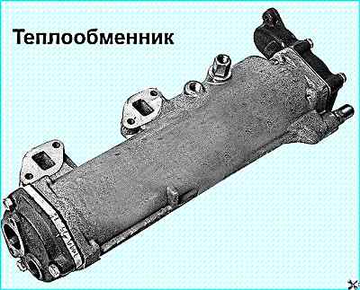
Coolant from the engine cooling system passes inside the tubes, and oil passes outside.
On the oil side, the tubes are finned in the form of cooling plates.
The oil flow in the heat exchanger crosses the tubes with water four times, which achieves high oil cooling efficiency.
Engine crankcase ventilation system: 1 - elbow, 2 - swirl valve, 3 - sealing ring; 4 pipe; 5 - inner bushing, 6 oil drain pipe. 7 - oil separator: 8 - angular hose; 9,10 - clamps; 11 gas outlet pipe; 12 throttle; 13 - clamp
The crankcase ventilation system (see figure) is open, cyclone type.
Crankcase gases are discharged from the rod cavity of the second cylinder, through the elbow 1, in which the swirler 2 is installed.
When the engine is running, the crankcase gases, passing through the swirler 2, receive a helical movement.
Due to the action of centrifugal forces, oil droplets contained in the gases are thrown to the wall of pipe 4 and through pipe 6 are drained back into the crankcase.
The purified crankcase gases are removed into the atmosphere.
Possible malfunctions of the diesel lubrication system and methods of elimination
Malfunction - Cause of malfunction
Remedy
Increased consumption oil
- Long-term engine operation at idle speed.
Do not operate the engine at idle speed unless necessary.
- Oil leakage through connections in the turbocharger lubrication system.
Tighten connections, replace gaskets and rubber sleeves if necessary.
- Wear of the valve-bushing connection in the cylinder head, aging of the rubber valve cuff.
Check and replace worn parts.
- Clogged air cleaner or air intake cap.
Service the air cleaner and clean the cap mesh.
Loss of oil pressure in the lubrication system
- Low oil level in the oil pan.
Check and if necessary add oil to the "B" mark
- Malfunction of pressure control devices
Make sure that the devices are working properly
- Use of oil of the wrong viscosity
Replace the oil with the one corresponding to the chemotological chart.
- Contamination of the filter elements of the oil filter
Replace the filter elements.
- Maladjustment or jamming of the safety valve or lubrication system valve
Check the valves and eliminate jamming, if necessary, adjust or replace faulty parts.
- Clogged oil pump intake
Flush the intake
- Coolant entering the oil
Check the tightness of the water cavity, the seal of the cylinder liners, the tightness of the water-oil heat exchanger, faulty parts replace.
- Oil leaks at the joints and oil lines of the lubrication system
Check the condition of the process plugs, plugs, tightening of fasteners at the joints, condition of the sealing rings and gaskets
- Malfunction of the oil pump
Remove the pump and check its operability on a special stand.
- Unacceptable increase in the clearance in the crankshaft and camshaft bearings
Repair the engine.
Lighting up of the emergency oil temperature indicator
- Malfunction of the emergency oil temperature sensor
Make sure the sensor is working properly, replace if necessary.
- Jamming of the heat exchanger switching thermal valve, malfunction of the thermal power sensor
Check the operation of the switching thermal valve heat exchanger, if necessary, eliminate jams or replace the sensor.
- Clogged tubes or dirty cooling plates
Check the water-oil heat exchanger for clogging pipes and cooling plate contamination, if necessary, flush or replace the heat exchanger.
Increased oil pressure in the lubrication system
- High oil viscosity
Change the oil to one that matches the chemotological chart
- Loss of tightness of the control signal line connecting the main oil line to the pump or its clogging
Check the oil supply pipe to the pump, the tightening of the mounting bolts, the presence of a hole in the cover
- Jamming or misadjustment of the lubrication system valve.
Check the valve and eliminate jamming, if necessary, replace faulty parts.
Repair of oil system components
To disassemble, assemble and check the oil pump:
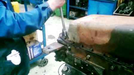
- — drain the oil from the crankcase, unscrew the mounting bolts and remove the crankcase;
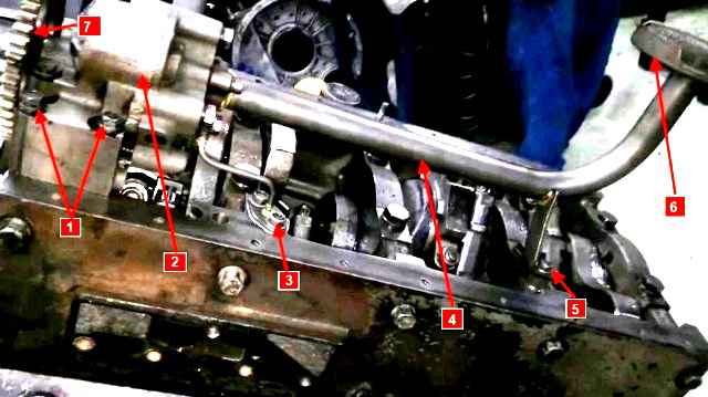
Engine oil system parts: 1 - mounting bolts oil pump; 2 - oil pump; 3 - bolts for fastening the supply pipe of the lubrication system valve; 4 - suction pipe; 5 - bolt for fastening the suction pipe; 6 - oil receiver; 7 - oil pump drive gear
- — remove the suction pipe 4 (Fig.) with the flange, bracket and cup assembly and the supply pipe of the lubrication system valve;
- — unscrew the oil pump mounting bolts 1, remove the pump;
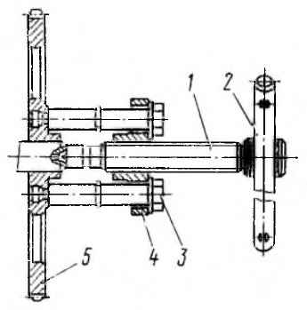
Removing the driven gear of the oil pump drive with the puller И801.02.000: 1 - screw; 2 - handle; 3 - bolt; 4 - crossbar; 5 - gear
- — remove the oil pump gear with the I80 1.02.000 puller (fig.), to do this, screw bolts 3 into gear 5 until they stop, and rest screw 1 against the end of the shaft.
Turning the handle, screw the screw into the crossmember until the gear is completely removed;
- — unscrew the bolts securing the pump and radiator sections of the oil pump and disassemble it;
- — measure the radial and end clearances of the pump and radiator sections, the clearances in the engagement of the gear teeth in the radiator and pump sections, between the drive shaft and the hole in the housing, between the axle and the gear.
Replace worn parts if necessary details;
- — when assembling the pump, do not reuse the bending washers.
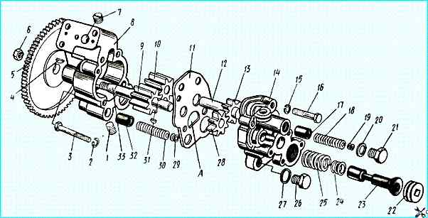
Oil pump: 1, 7 - oil channel plugs, 2, 15,19 - washers, 3, 16 - bolts, 4, 31 - segment keys, 5 - oil pump drive gear, 6 - nut, 8 - pump section housing, 9, 28 - drive gears, 10,13 - driven gears, 11 - spacer, 12 - driven gear axle, 14 - radiator section housing, 17 - safety valve, 18, 25, 30 - springs, 20 - gasket, 21, 22, 26 - plugs, 23 - lubrication system valve, 24, 29 - washers, 27 - gasket, 32 - safety valve, 33 - shaft
After assembling the pump, the shaft should rotate smoothly by hand, without jamming;
- test the pump on a stand using M10G2K or M10DM oil.
With a shaft rotation speed of 2800 - 60 min -1 and a vacuum at the suction of 12-15 kPa, the pump flow should be at least 130 l/min at an outlet pressure of 0.35 - 0.40 MPa;
- adjust the operating pressure of the lubrication system valve, which should be 0.40 - 0.45 MPa.
No more than 3 washers installed under the spring are allowed for adjustment.
If the pressure-start of valve opening does not match, replace the spring. Reuse of the plug cotter pin is not allowed.
Tightening torques of threaded connections, Nm (kgcm)
- Oil pump mounting bolts 49.0 - 68.6 (5 - 7)
- Cover mounting bolts 39.2 - 54.9 (4 - 5.6)
- Pump tube mounting bolts 19.6-24.5 (2-2.5)
- Oil filter caps 49.0- 58.8 (5 - 6)
- Filter thermovalve plug 47.0- 58.8 (4.8 - 6)
- Cap drain plugs 24.5-39.2 (2.5-4.0)
- Oil filter mounting bolts 88.2-112.6 (9.0-12.5)
- Oil pump drive driven gear mounting nut 98.1-117.6 (10-12)
Dimensions of parts and permissible wear, mm
- Gear diameter 55.44 - 55.47
- Permissible diameter of gears 55.4
- Radial clearance between gear teeth and housing wall 0.130-0.206
- Permissible radial clearance 0.25
- Gear height 34.913 -34.975
- Permissible gear height 34.900
- Well depth 35.050-35.089
- End clearance 0.075-0.176
- Permissible end clearance 0.2
- Roller journal diameter 19.920 - 19.899
- Permissible journal diameter 19.85
- The diameter of the bushings in the housing for the roller necks is 19.98-19.959
- Permissible diameter of bushings 20.10
- Axle diameter 19.987 - 20.000
- Allowable axle diameter 19.85
- Diameter of driven gear bushings 20.040-20.073
- Allowable bushing diameter 20.080
- Valve plunger diameter 15.968-15.941
- Allowable plunger diameter 15.92
- Diameter of the hole in the valve cover 16,000-16,027
- Valve spring force compressed to 44 mm, N 60-74
To disassemble, assemble and check the oil filter:
- - drain the coolant from the engine cooling system;
- - unscrew the drain plugs from the caps and drain the oil from the filter;
- - disconnect the coolant supply and outlet pipes to the heat exchanger;
- - unscrew the five mounting bolts and remove the filter with the heat exchanger;
- - unscrew the nuts and disconnect the heat exchanger from the filter;
- - unscrew the caps from the housing, flush the internal cavity with diesel fuel, check the integrity of the sealing rings, thrust springs, replace if damaged;
- - check the assembled filter for leaks with compressed air 490 kPa in water;
- - check the pressure at which the bypass valve starts to open, which should be 0.147-0.216 MPa;
- - check the operability of the heat exchanger switching thermal valve.
At an oil temperature of (50-70) °C, the flow rate through the valve should be at least 70 l/min at a pressure of 0.147 kPa and no more than 5 l/min at a temperature of 100-110 °C.
If necessary, replace the thermal power sensor TS 103-1306090-30.
To disassemble, assemble and check the operation of the water-oil heat exchanger:
- - install plugs on the oil supply flanges and pressurize the oil cavity with a pressure of 0.79-0.83 MPa in water, if leaks are detected, remove the inlet and outlet manifolds of the heat exchanger and remove the core from the housing, replace the sealing rings or, if the tubes are damaged, the core.