• Auto-hand
    • Lada Granta
    • Lada Kalina
    • VAZ-2121
    • Lada-Largus
    • Lada Priora
    • Lada Vesta
  • separator
    • GAZ-66
    • GAZ-2705
    • GAZ-3110 (Volga)
  • Separator-2
  • Engines
    • UAZ 3151
    • Niva Chevrolet
    • ZIL-5301
    • MAZ
    • Ural car
    • ZIL-131
    • Auto PAZ
    • Kamaz
  • Separator-3
  • Systems
  • separator-4
  • search

Select your language

  • Русский
  • Қазақша (kk-KZ)
  • Українська (Україна)
  • Español (España)
  • German (DE)
  • English (UK)

Installation of fuel injection pump and ZIL-5301 injectors

Installation of high-pressure fuel pump, injectors, high-pressure and low-pressure pipes ZIL-5301

The high-pressure fuel pump mating plate must be clean; nicks and other damage to the plate are not allowed

Brake malfunctions ZIL-5301

Possible malfunctions of ZIL-5301 brakes

If, when you press the brake pedal, you feel a sharp braking of the front brake with it being pulled to the side, then the front wheel pads have clearly worn out completely, and because of this, the brake disc is worn out

Maintenance of the D-245E3 lubrication system

To ensure normal operation of the diesel engine, observe the following requirements for servicing the lubrication system:

  • - fill the oil sump with only the oil recommended by the manufacturer.

Features of the ZIL-5301 vehicle

The vehicle is manufactured and designed for operation at ambient temperatures from plus 40 to minus 40°C, relative air humidity up to 80% at 20°C, air dustiness up to 0.1 g/m 3

Removal and disassembly of the cardan shaft ZIL-5301

Removing and disassembling the ZIL-5301 cardan transmission

To remove the cardan transmission from the vehicle, unscrew the nuts securing the rear fork-flange of the cardan shaft, remove the washers and remove the bolts from the flange holes, while supporting the cardan shaft.

ABS modulator ZIL-5301

The ABS modulator is designed to control the air supply to the pneumatic chambers of the main cylinders
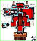
Fuel supply control drive ZIL-5301

The fuel supply drive device is shown in Fig. 1.

The drive can be disassembled and assembled in any sequence.

When assembling the drive, it must be adjusted in the following order:

Page 13 of 42

  • 8
  • 9
  • 10
  • 11
  • 12
  • 13
  • 14
  • 15
  • 16
  • 17