Repair ZIL-5301
The ZIL-5301 "Bychok" is a light-duty truck whose specifications vary depending on the model, but generally speaking, it features a 4.75-liter diesel engine (producing between 109 and 130 hp), a payload capacity of approximately 3–3.5 tons, and a top speed of 95 km/h.
Key features include rear-wheel drive, a five-speed manual transmission, and reinforced suspension with leaf springs.
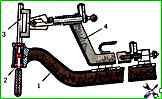
When repairing, the front axle beam must be checked for bending and twisting on a device (Fig. 1), which is installed on the spring platform
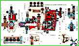
Assembly of the 4UTNI-T-1111005-50 high-pressure fuel pump for the ZIL-5301 vehicle
Before assembly, the low-pressure cavity of the pump must be flushed with diesel fuel under a pressure of 1.8-2.0 MPa. filtered M10G2 motor oil should be used to lubricate the pump and regulator parts
")

")
")
")
")
")
")
")