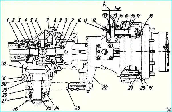
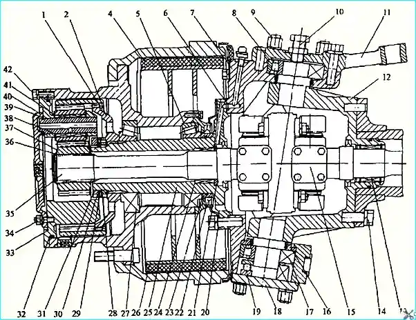
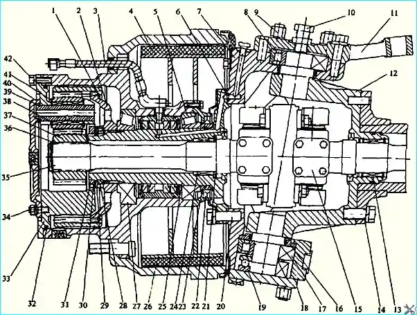
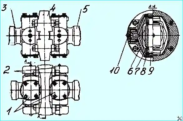
The design of the front axle central gearbox is shown in Fig. 1, wheel gears and kingpin device in Fig. 2, 3, constant velocity joint in Fig. 4
Maintenance of the front drive axle consists of maintaining the required oil level and replacing it in a timely manner; checking the seals and tightening the threaded connections.

Fig. 1. Central gearbox and wheel brake drive device: 1 - stopper; 2 - nut; 3. 28, 29 - bearing; 4, 10 - hinge fist; 5 - differential; 6 - axle housing: 7 - driven gear; 8 - cover; 9, 11, 19, 24, 30 - bolt: 12, 20 washer; 13 - expander cam lever; 14 - adjusting washers; 15 - expander cam; 16, 21 sealing ring; 17 - support sleeve; 18 - tension spring; 22 - lever; 23 - transverse rod; 25 - sealing ring: 26 - flange: 27 - cuff; 31 — adjusting shim: 32 — driving gear
The constant velocity joint bearings are lubricated regularly according to the lubrication chart, and more frequently when operating in very dusty and dirty conditions.

Fig. 2. Wheel drive and kingpin: 1, 36, 39 — retaining ring: 2 hub: 4. 26 — brake shoe: 5, 8, 13, 17, 19, 28, 24, 27, 38 — bearing: 6. 32 - sealing ring: 7 — steering knuckle: 9, 14, 20, 34, 42 - bolt: 10 - adjusting bolt: 11 steering knuckle lever: 12 - support: 15 - joint knuckle: 16 - thrust washer: 18, 40 — cover; 21 — thrust ring; 22 — cuff; 23 — bushing; 25 - journal: 28, 31, 34 - nut; 29, 30, 41 washers: 33 - carrier: 35 - outer hinge fist; 37 - drive pinion
To lubricate the hinge bearings, turn the wheel, or to the left as far as it will go, unscrew all plugs 10 (Fig. 4) and, screwing in the grease nipple sequentially, fill the cavity of the crosspiece 6 with grease until it appears in the opposite hole.

Fig. 3. Wheel gear (with central shaft) and kingpin device: 1, 36, 39 - retaining ring; 2 — hub; 3 — air duct; 4, 26 — brake shoe 5, 8, 13, 17, 19, 28, 24, 27, 38 — bearing 6, 32 — sealing ring; 7 — steering knuckle 9, 14, 20, 34, 42 — bolt 10 — adjusting bolt 11 — steering knuckle lever; 12 — support; 15 — hinge knuckle; 16 — thrust washer: 18, 40 — cover 21 - thrust ring 22 — cuff; 23 — bushing; 25 — journal; 28, 31, 34 — nut; 29, 30, 41 — washer; 33 - carrier 35 -- outer knuckle joint 37 — pinion gear
Periodically check the tightening of the bolts securing the cover and supports to the axle housing, the nuts securing the pinion housing to the axle beam, the nuts securing the bearing caps of the kingpins and the steering knuckle arm, the bolts securing the carrier to the wheel hub.

Fig. 4. Constant-velocity joint: 1 - cover, 2 - needle bearing housing. 3 — outer hinge fist, 4 — hinge cage, 5. inner hinge fist, 6 — hinge crosspiece, 7 — sealing ring, 8 needle bearing, 9 — crosspiece pin, 10 — plug
Adjustment of bearings 28, 29 (Fig. 1) of leading bevel gear 32 is similar to adjustment in the central gearbox of the rear axle.
Adjustment of the engagement of bevel gears is similar to that of the middle axle.
The difference is that adjustment of bearings 3 of the differential and engagement of gears is carried out directly on the axle without disassembly.
In this case, the tension of the conical bearings of the differential is carried out by adjusting nuts 2 through the holes in the axle beam with the stopper 1 removed.
Lubrication of bearings 17, 19, 8 kingpins (Fig. 2, 3) are adjusted through grease nipples installed on each kingpin: on top on the cover and lever, on the bottom - at the back on the steering knuckle.
The kingpin bearings are adjusted on the suspended bridge with bolt 10, ensuring a gap of 0.1-0.2 mm between the end of the bolt and the kingpin by screwing the bolt in until it stops and then unscrewing it by 1/10 - ⅛ of a turn.
Front axle repair
Repair of the front steering drive axle (FSA) consists of replacing worn or damaged parts after disassembling the unit and removing damaged parts.
- 1. Disassemble the bridge after removing it from the vehicle in the following sequence (Fig. 1, 2, 3):
- 1.1. Drain the oil from the central gearbox housing torus and wheel gears, having first unscrewed all the plugs in the crankcase, hubs and wheel gear covers.
- 1.2. Disconnect the transverse rod 23 (Fig. 1) from the trapezoid arms, having unscrewed the fastening nuts, having first removed the cotter pins.
- 1.3. Remove the covers 40 (Fig. 2, 3) of the wheel gears with gaskets, having unscrewed the nuts 34 of the studs and the back washers.
- 1.4. Remove the carrier 33 of the wheel gears, having unscrewed the bolts 42 and removed the washers. Remove the rubber sealing ring 32.
- 1.5. Remove the drive gears 37 of the wheel gears, after removing the retaining rings 36 from the knuckles of the hinges 15. Inspect the parts and replace them if damaged.
- 1.6. Remove the hubs of 2 gears with driven gears, for which:
- — bend back the tab of washer 30, unscrew and shine lock nut 31, remove washer with pin 29 and unscrew nut 28;
- — remove the gear hub from the driven gear of the wheel transmission, remove the retaining ring 1 and take the hub out of the gear.
Possible malfunctions of drive axles and methods for their elimination
- Reason - Method of elimination
Increased heating of the axle:
- - Excessive or insufficient amount of oil in the gearbox and wheel transmission housing - Check and bring the oil level in the housings to normal
- - The engagement adjustment of the bevel gears of the main transmission is disturbed - Adjust gear engagement
- - Misaligned gearbox and hub bevel bearings - Adjust bearings
Increased axle noise:
- - Misaligned bevel gear engagement of final drive - Adjust gear engagement
- - Wear of bevel bearings of drive pinion of final drive and interwheel differential or misalignment of their adjustment - Check bearing condition, replace and adjust their tightening if necessary
- - Excessive gear wear - Replace worn gears
Increased axle noise when turning:
- - Increased wear of gears, satellite bushings and differential thrust washers - Disassemble differential and replace worn parts
Noise in the wheel reduction gear:
- - Wear of wheel gear pinions and satellite bearings - Replace worn parts
- - Insufficient oil level - Add oil to the wheel transmission housing
Oil leak through seals:
- - Wear or damage to cuffs - Replace cuffs
1.7. Removing and disassembling the wheel hub:
- — attach a puller to the hub, remove the hub assembly with the journals, having previously anchored or supported it.
Determine the presence of defects by visual inspection and, if necessary, disassemble to replace parts in the following order:
- — install the hub with the drum facing up and remove the cover with the cuff, checking for grease in the cuff area of the cover, removing the cover with cuffs and gasket, as well as the inner bearing rings;
- — unscrew the air duct 3 from the adapter, and the adapter from the air supply head housing (with the central bearing shaft);
- — remove the air supply head, removing the inner bearing ring, and remove the sealing rings (with the central bearing shaft);
- — if there is damage to the parts, repair replacement.
- 1.8. Remove shoes 4, 26, having first removed spring 18 (Fig. 1), bolts, remove washers and plates of shoe axles and take out sealing rings.
- 1.9. Before removing expanding fists 15, unscrew bolts 11 fastening washers of adjusting levers (left, right) and remove spring and thrust washers.
Before removing fists, first remove adjusting washers 14, support bushing 17 and sealing ring 16.
- 1.10. Remove bushing 23 from journal 25 (Fig. 2, 3) and take out rubber sealing ring.
- 1.11. Removing and disassembling the journal:
- — unscrew the bolts 20 securing the journal to the steering knuckle 7, remove the washers, oil catch can with gasket;
- — remove the journal 25 left (right) and the sealing rings 6 holes for the central bearing cap and breather (holes for the central bearing cap — along the axis of symmetry of the flange and the groove milling). If necessary, use a puller to remove the seal 22, remove the thrust ring 21.
Determine the condition of the seal, ring and bearing in the journal and the journal surface by visual inspection and measurement.
When replacing a bearing, use a puller to remove it from the journal.
1.12. Remove the joints after removing the journals, supporting the inner knuckle to prevent damage to the cuff and bearing in the support.
Determine the operating condition of the surfaces of the joint knuckles under the cuff and bearing by visual inspection.
Replace the joints if the working surfaces are significantly worn.
1.13. Disassembling the central gearbox and removing the crankcase cover with the differential.
Before removing the drive gear 32 (Fig. 1), it is necessary to remove the steering knuckles 7 (Fig. 2, 3) and supports 12 in the following sequence:
- — unscrew the nuts 9 of the studs securing the lever 11, the upper cover, the lower it covers and mounting bolts;
- — remove levers 22 (Fig. 2) of the steering trapezoid, unscrew the bolts securing the lever to the steering knuckle, having first unpinned them and removed the lower cover 18 (Fig. 2, 3) with gaskets;
- — remove the thrust washer (when installing a thrust roller bearing instead of a ball bearing), the thrust bearing with spacer washer 16 and rings after removing the bearing 17;
- — remove the steering knuckle 7 from the upper kingpin of the support 12. To remove the supports, it is necessary to unscrew the bolts 14 securing the supports to the flanges of the crankcase 6 (Fig. 1) and cover 8 and the shock absorber brackets without washers, remove the sealing ring;
- — check the condition of the cuff and needle bearing. If replacement is necessary, remove the seal and bearing with a puller, removing the retaining ring.
To remove the pinion gear, unscrew the bolts securing the pinion gear housing 32 to the axle housing, removing the washers.
After removing the pinion gear, remove the adjusting linings 31 (sealing linings, if any).
Remove the cover 8 after unscrewing the bolts 9 securing the cover to the axle housing without washers, then remove the lining.
Remove the differential 5 with the gear 7 from the axle housing 6.
Remove the pinion gear, cover and differential with the axle beam in a vertical position (cover at the top).
Determine the technical condition of the cover and axle housing by visual inspection; replace the parts if defects are found.
- 1.14. Disassemble, check and adjust the pinion gear, differential, central and wheel reduction gear in the same way as the rear axle.
- 1.15. Assemble the front drive axle in the reverse order of disassembly. All rubbing parts must be lubricated with transmission oil, cuffs with Litol-24 grease.
- 1.16. Install the hub with the central bearing cap on the journal after installing the protective cover on the journal to protect the head cuffs from damage.


