The lighting fixture connection diagrams are shown in Fig. 1 and 2
The lighting system includes headlights, spotlights, fog lights, front and rear lights, reversing lights, cabin and berth lights, an underhood light, lamps and a set of switching equipment (switches, relays, etc.).
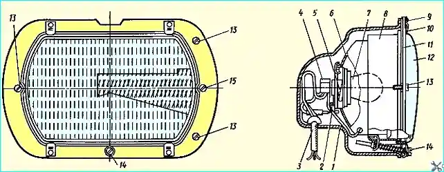
The headlight (Fig. 3) is rectangular, which significantly improves light distribution on the road surface.
The headlights have a European asymmetric lighting system, eliminating the blinding of oncoming drivers.

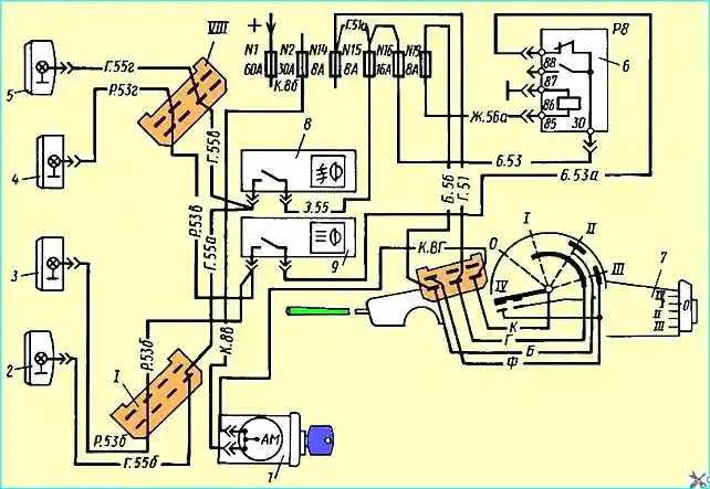
Fig. Wiring diagram of spotlights and fog lights: 1 - instrument and starter switch; 2, 5 - fog lights; 3, 4 - spotlights; 6 - relay P8 for blocking spotlights; 7 - steering column switch; 8 - fog light switch; 9 - spotlight switch; I, VIII - plug connectors
The front lights are combined in one housing with the direction indicators. The side light lenses are white, the direction indicators are orange.
The rear light has a side light and a red brake light, as well as a direction indicator with an orange diffuser.
The left rear light also has a white diffuser at the bottom for illuminating the license plate.

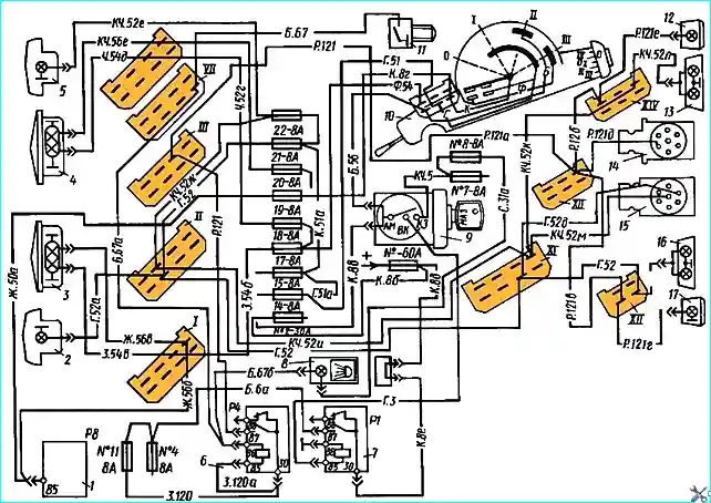
Fig. Lighting system diagram: 1 - relay P8 for blocking the headlights-spotlights; 2, 5 - front side lights; 3, 4 - headlights; 6 relay P4 for disabling the reversing lights; 9 — instrument and starter switch; 10 — steering column switch; 11 relay P4 switch; 12, 17 — reversing lights; 13, 16 — tail lights; 14, 15 — trailer power plugs; I, II, III, VII — plug connectors
The FG 152 fog light is made with a white rectangular diffuser.
The headlight is equipped with a halogen lamp, which, together with a special diffuser, provides good illumination of the road in poor visibility conditions (fog, rain, etc.).
External lighting is controlled using switch 10 (see Fig. 2).
The switch handle has 5 positions
- 0 — everything is off;
- I — parking lights are on;
- II — parking lights and low beam are on;
- III — parking lights and high beam are on;
- IV- parking lights and high beam are on for operation in flashing mode mode
Position IV of the switch is not fixed: when you remove your hand from the switch handle, the latter returns to its original position.
All five switch positions are marked with corresponding symbols indicating which lighting device is on.

Fig. Headlight: 1 - protective cap; 2 - flat spring; 3 - wires; 4 - connecting block; 5 - spring; 6 - reflector; 7 - lamp; 8 - headlight housing; 9 — rivets; 10 — lens mounting bracket; 11 — bezel; 12 — lens; 13 — headlight mounting screws; 14 — vertical adjustment screw; 15 — horizontal adjustment screw
The fog lights and spotlights are switched on by separate switches, and the spotlight switching circuit uses a lock that prevents the headlights from being switched on with low beam.

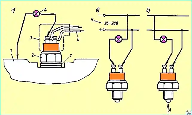
Fig. Checking the reversing light switches: 1 - gearbox; 2 - switch; 3 - cover; 4 - indicator lamp; 5 - power source; 6 - white wire; 7 - gaskets
During operation, it is necessary to monitor the cleanliness of the diffusers and wash or wipe them with a rag before leaving.
Dirty lighting devices sharply reduce light output, which impairs both the visibility of the lights and the illumination of the road by the headlights.
In such lighting devices as headlights, lanterns and lampshades, reflectors darken or the housings and diffusers break under operating conditions.
If the diffusers fail, they are replaced with new ones.
If the housings break and the reflectors darken, the entire device is replaced.
List of lamps, note changed in lighting devices:
- Headlight 8704.24 - A24-55-50
- Fog light FG152 - HI type AKG24-70
- Spotlight 20.3711 - HI type AKG24-70
- Front light PF130B - A24-21-2
- Rear light
- FP130V-left - A24-21-2- 2 pcs.
- FP130G-right - A24-21-2- 2 pcs.
- Side turn signal 14.3726 - A24-5
- Identification lamp of the road train PF233 - A24-5
- Cab interior light 11.3714 - A24-21-2
- Sleeper berth light PK124V - AC24-5
- Reversing light FP135B A24-21-2
- Control and signal lamp units PD511B, PD512B - A24-2, 6 pcs. in the block
- Instrument cluster 13.3801 - A24-2 – 5 pcs
- Pressure gauge UK 168 - A24 – 2 – 2 pcs
- Speedometer SP 152 - A24 – 2 – 2 pcs
- Hazard warning switch VK 422 – 24 - AMN24 - 3
It should be remembered that a dark coating sometimes appears inside the lamp bulb, which is a consequence of the deposition of filament evaporation products on the bulb.
This phenomenon significantly worsens the light output, and it is advisable to change such lamps without waiting for their final failure.
This is especially important for headlights, on which the quality of road illumination depends.
If the headlights are replaced, then after their installation on the vehicle, they should be adjusted according to the procedure described in the vehicle operating manual.
The switching equipment is quite durable and, as a rule, does not fail under operating conditions.
In the event of a product failure, it must be replaced, since switches and toggles cannot be repaired.
Possible malfunctions of the lighting system and how to fix them
- Cause of malfunction - Method of elimination
Headlights do not light:
- - Fuses No. 17 and 18 for high beam headlights and No. 19 and 20 for low beam have blown - Replace fuses
- - Bulbs have blown - Replace bulbs
The "high beam" indicator lamp does not light:
- - Fuse No. 17 - Replace the fuse
- - The lamp has burned out - Replace the lamp
- - The control lamp unit is faulty - Replace the unit or repair
The reversing lights do not turn on:
- - Fuse No. 11 has burned out - Replace the fuse
- - Switch 11 is faulty or not adjusted - Replace or adjust the switch setting
If relays P1, P4, P8 fail, they are checked as specified in the section "Electric torch device" and replaced if necessary.
If a non-standard fuse was installed in the control and signal lamp units, the current-carrying tracks of the printed circuit board may melt due to short circuits.
A burnt-out track is repaired by soldering with solder or soldering of copper wire.
If the reversing lights fail, check fuse #8, if it is working properly, check switch 2 (Fig. 4).
To check, remove protective cover 3 from the switch (Fig. 4, a).
If there is voltage at the switch terminal where the white wire is connected, but the reversing lights do not light when the gear shift lever is set to the "Reverse" position, then you need to remove the switch and check it.
To check the serviceability of the switch, connect the "+" of the 26 - 28 V voltage source to one terminal of the switch with a wire with a clamp, and connect the other terminal through the test lamp to the "-" of the source (Fig. 4, b).
In this position, the test lamp should not light.
If you press the switch ball in the direction of arrow A (Fig. 4, c) and push it in until it stops (approximately 1.5 - 2.5 mm), then the control lamp should light. If the lamp does not light, the switch is faulty and must be replaced.
If the switch is in good condition, then its position is not adjusted on the gearbox cover.
Adjustment is made by installing or removing the adjusting linings located on the threaded part of the switch.


