The crankshaft is made of steel, manufactured using the hot stamping method. The journals of the shaft are hardened with heating by high-frequency currents.
The crankshaft has four main bearings and three connecting rod journals.
The latter have internal cavities closed with plugs, where the oil undergoes additional centrifugal cleaning.
These cavities communicate with transverse channels in the main journals by inclined channels.
To balance the engine and unload the main bearings from the inertial forces of the reciprocating masses of the pistons and connecting rods and unbalanced centrifugal forces, counterweights are installed on the cheeks of the crankshaft, in assembly with which the shaft is balanced.
In addition, the balancing system includes two remote masses, one of which is made in the form of a lug on the flywheel, the other is a counterweight installed on the front end of the crankshaft shaft.
The axial fixation of the shaft is carried out by four bronze half rings installed in the grooves of the rear main bearing.
To prevent rotation, the lower half rings enter with their grooves into the pins pressed into the rear main bearing cover.
The nose and tail of the crankshaft are sealed with rubber self-tightening cuffs.
The engines are equipped with a crankshaft 2Z6NE-1005009 (marking 236N-1005015-U)
The crankshaft is marked on the 5th cheek.
The liners of the main bearings of the crankshaft and the lower head of the connecting rod (Fig. 1) are replaceable, thin-walled, have a steel base and a working layer of lead bronze.
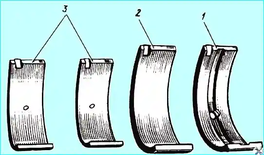
Fig. Crankshaft bearing shells: 1 - upper main bearing shell; 2 - lower main bearing shell; 3 - connecting rod lower head liner
The upper and lower crankshaft main bearing shells are not interchangeable.
The upper shell has a hole for supplying oil and a groove for distributing it.
The connecting rod lower head liners are interchangeable.
On YaMZ-2Z6BE, YaMZ-236B, YaM3-2Z6NE and YaM3-236N engines, oil is supplied to the connecting rod upper head bushing and piston pin through the hole in the liner.
Installing the crankshaft on the engine
When installing the crankshaft on the engine, ensure that the bearing shell sizes correspond to the shaft journal sizes.
Before installation, ensure that the outer surfaces and internal cavities of the crankshaft and other mating surfaces.
Lubricate the journals and working surfaces with clean engine oil.
To facilitate installation of the flywheel in the correct position relative to the crankshaft, the number "6" is applied to the flywheel hub, which must be aligned with the number "2" on the end of the crankshaft during assembly.
The main bearing caps are not interchangeable; When installing them, ensure that the stamp on the cover matches the stamp on the block.
Start tightening the main bearing caps with the vertical bolts and tighten in two steps with a torque of 430-470 Nm (43-47 kgfm) after repeated tightening, then tighten the horizontal bolts in two steps with a final tightening torque of 90-120 Nm (9-12 kgfm).
Before tightening the rear thrust main bearing, align the axial clearance by slightly tightening the bearing cap with bolts and moving the crankshaft back and forth in the axial direction until it stops using a crowbar, first back, then forward, aligning the position of the cap.
After tightening the bolts, check the axial clearance with a feeler gauge. It should be the same on both sides of the cover.
The crankshaft journals can be of two nominal sizes and therefore the following marking options and the use of the corresponding liners are possible.
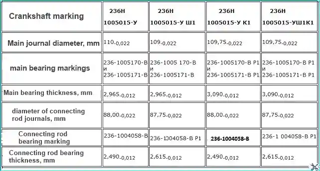
Note: The letters "N", "U", "Sh", "K" and the number "1" are stamped during marking by impact.
Replacing the crankshaft gear
The crankshaft gear can be replaced without removing the crankshaft from the engine.
With the pulley and front block cover removed, press the front counterweight and gear using puller.
Before installation, heat the gear and front counterweight to a temperature of 105-155°C and press them sequentially until they stop using a special device.
Cleaning the cavities of the connecting rod journals
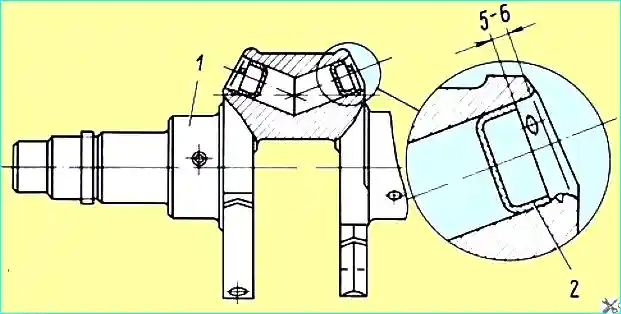
Fig. Plugs of the cavities of the connecting rod journals: 1 - crankshaft; 2 - plugs
Each time the crankshaft is removed from the engine to replace the liners, clean the cavities of the connecting rod journals, having previously removed the plugs 2 (Fig. 2), which close the cavities.
Replace the plugs with new ones, their reuse is not allowed.
Before installing the plugs, file down the metal swelling at the edges of the holes from the previous punching, wash the shaft and blow out the oil channels.
Press the plugs to a depth of 5-6 mm from the edge of the hole, then punch inside the hole at three points equally spaced around the circumference to prevent spontaneous pressing out of the plugs.
Basic requirements for grinding crankshaft journals
Grind the crankshaft journals to repair dimensions within the specified dimensions, while ensuring that the following requirements are met:
- 1. When regrinding the shaft journals to repair dimensions, ensure a smooth radius of 6-0.5 mm for the transition from the journals to the cheeks without undercuts, burns, or rough scratches; the surface roughness of the journals should not exceed 0.20 μm, and the fillet radii should not exceed 0.32 μm.
- 2. The value of the radii of the axes of all shaft cranks should be 70±0.12 mm.
- 3. The tolerance of the parallelism of the axes of the middle main journals relative to the common axis of the outer main journals should not exceed 0.010 mm, the tolerance of the parallelism of the axes of the connecting rod journals relative to the common axis of the outer main journals should not exceed 0.03 mm over a length of 100 mm or 0.022 mm over the length of the journal.
- 4. Ovality, taper, concavity and barrel-shapedness of main and connecting rod journals are not allowed to exceed 0.005 mm.
- 5. Cracks on the shaft surface are not allowed. Check for surface defects with a magnetic flaw detector followed by mandatory demagnetization.
When installing the crankshaft, it is necessary to ensure a diametrical gap between the crankshaft main journals and the liners within 0.07-0.12 mm.
To do this, it is necessary:
- - check that the liners match the crankshaft journal sizes.
The liners are checked according to the marks that the manufacturer places on the outer surface of the liners;
unscrew the main bearing cap fastening bolts and remove the caps.
Wipe the joint planes and bearing seat in the cylinder block and main bearing caps;
- - remove the packaging from the main bearing shell kit and wipe them.
Install the upper liners with a hole and a groove in the sockets located in the cylinder block, and the lower liners - in the main bearing caps, aligning the locking locks with the grooves in the sockets.
- - install the caps on the cylinder block, screw in the bolts by hand 1 - 2 threads and tighten them with a torque of 300 - 320 Nm (30 - 32 kgfm).
When tightening the bolts, it is necessary to lightly tap the cap with a rubber hammer;
- - measure the diameters of the main bearing holes with an indicator bore gauge 100-160 mm, the diameters of the crankshaft journals with a micrometer 100-150 mm.
The difference in readings will give the the gap that will be after installing the crankshaft.
If the readings do not fit within the permissible diametrical gap, then it is necessary to select another crankshaft or select liners by thickness from the same size group.
After selecting the liners and crankshaft by diametrical gap, remove the main bearing caps, having previously unscrewed the bolts.
Before installing the crankshaft in the cylinder block, it is necessary to clean the sharp edges of the lubrication holes with a scraper or a tucked bar, wipe and lubricate the upper liners of the crankshaft bearings with diesel oil.
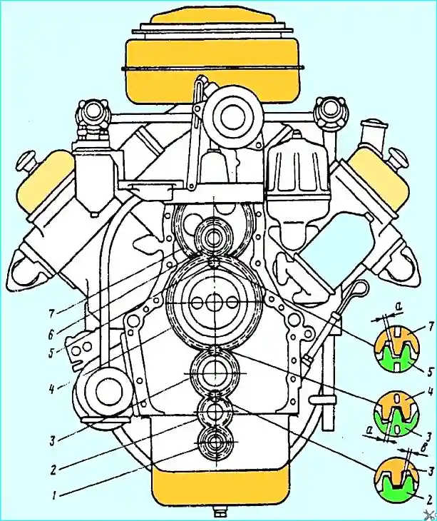
Fig. Gears: 1 - oil pump drive; 2 - intermediate oil pump drive; 3 - crankshaft; 4 - camshaft; 5 - drive pinion of fuel pump; 6 - fan drive; 7 - fuel pump drive slave
When installing the crankshaft in the cylinder block, it is necessary to wipe the journals and align the "O" marks on the tooth of gear 3 of the crankshaft and the cavity of gear 4 of the camshaft (see Fig. 3).
Then install the thrust half rings of the crankshaft in the grooves of the rear main bearing of the cylinder block so that the side with the grooves adjoins the thrust ends of the shaft.
Preliminarily, the half rings must be wiped and lubricated with diesel oil.
After installing the shaft, it is necessary to lubricate its main journals with diesel oil.
When installing the crankshaft rear bearing cover, it is necessary to wipe the liners and install the thrust bearing half rings on the cover so that the side with the grooves adjoins the thrust ends of the shaft.
After of this, install the previously removed covers, having previously wiped the liners.
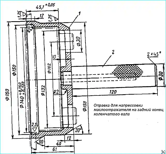
Fig. Mandrel for pressing the oil deflector onto the rear end of the crankshaft
When installing the covers, it is necessary to ensure that the serial number of the cover matches the serial number of the support on the cylinder block, with the stamped side of the cover facing the left row of cylinders.
The numbering of the supports on the block starts from the front end of the cylinder block.
The bolts are tightened with a torque wrench to 300-320 Nm (30-32 kgfm).
In this case, the bolts of the intermediate supports and the front support are tightened, and the bolts securing the crankshaft rear bearing cover are tightened after adjusting the clearance in the thrust bearing.
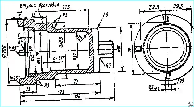
Fig. Key for tightening the front counterweight mounting nut
The bolts are tightened sequentially in two stages (preliminary and final tightening), starting with the middle bolts and ending with the outer ones.
The axial clearance is checked with a set of feeler gauges by moving the crankshaft along the axis in both directions.
The clearance should be within 0.08-0.23 mm.
It is necessary to check at two opposite points through 180°.
After tightening the rear main bearing mounting bolts with a torque of 300-320 Nm (30-32 kgfm), the clearance fluctuation for one thrust half rings should not exceed 0.05 mm.
The gap on both sides of the cover should be the same.
After tightening the bolts, the crankshaft should turn easily without jamming from the force of the hand applied to the flywheel mounting pins.
The bolts securing the main bearing cover are protected from loosening with a locking wire.
Then install and press the rear oil deflector onto the rear end of the crankshaft with a mandrel (Fig. 4) and lock it by pressing metal into four holes on the crankshaft.
Install the front oil deflector and lock washer onto the front end of the crankshaft and screw on the front counterweight mounting nut by hand.
After this, lock the crankshaft from turning with a stop inserted into the counterweight hole, tighten the nut with a wrench (Fig. 5) to a torque of 180-320 Nm (18-32 kgfm) and lock it with a washer.


