Removing the camshaft
Remove the axial lock of the camshaft (650.1006236) by unscrewing the 2 screws securing it (310145)
Remove the camshaft assembly with the gear.
Removing the camshaft bushings
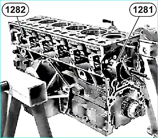
Only in case of replacement, remove the bushings using tools 1281 + 1282 (see Fig. 1)
Disassembling the camshaft
- 1. Only in case of replacement, remove the gear (650.1006214) using a press.
- 2. Remove the key (314009).
Checking the valve timing components
Check the camshaft according to the following parameters:
- - journal diameter;
- - diameter of the seating surface for the camshaft gear;
- - radial runout of the camshaft main bearings.
Assembling the camshaft
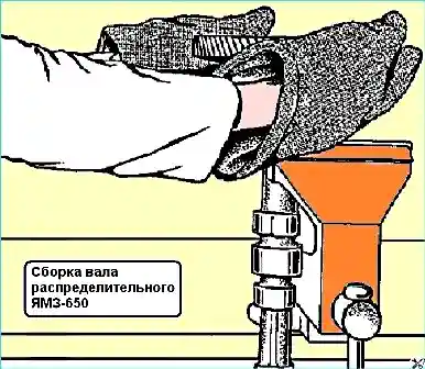
- 1. Install the key in the camshaft groove.
- 2. Heat the gear to 200˚ C (minimum heating time - 60 minutes).
- 3. Install the gear (see Fig. 2).
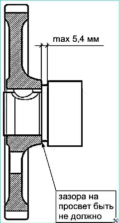
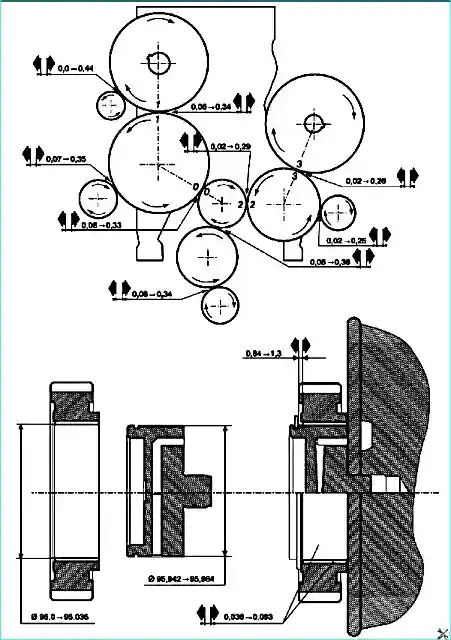
- 4. Check the gap at three points between the end of the camshaft bearing journal and the end of the gear hub, which should be no more than 5.4 mm (see Fig. 3).
- 5. let cool.
Installing the camshaft
- 1. Cool the camshaft bushings in liquid nitrogen or 12 hours in a freezer.
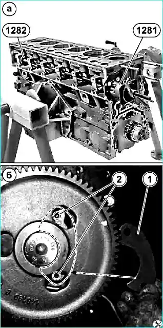
- 2. Install the bushings in the cylinder block, aligning the lubrication holes. To do this, use tools 1281 + 1282 (see Fig. 4a).
- 3. Lubricate the working surface of the bushings with engine oil.
- 4. Install the camshaft, aligning the marks (1-1) (see Fig. 5).
- 5. Install the axial locking pin in the gap between the journal of the camshaft and the gear.
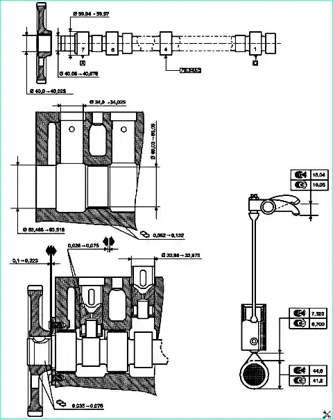
- 6. Fasten the axial locking pin of the camshaft (1) to the block through the holes in the gear with two screws (2) with a torque of Мкр = 30 ± 6 Nm (apply sealant "Loctite 542" to the threads of the bolts) (see Fig. 4B).
- 7. Check the interdental and lateral clearance (see Fig. 6).
Devices for removing and installing the camshaft
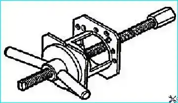
1281 Puller 5000261281
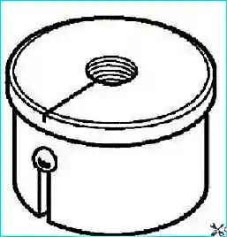
1282 Punch 5000261282


