During repair, the gearbox of the MAZ-5335 vehicle and its modifications is disassembled in three stages: partial disassembly, general disassembly of units
During partial disassembly, the following operations are performed
- - Unscrew the oil drain plugs, remove the bolts securing the cover of the oil pump 20 (Fig. 1) from the gearbox together with the magnet, and remove the gasket of the cover of the oil pump from the gasket.
- - Unscrew the nuts of the remote gear shift mechanism to the upper roof, remove the spring washers, the mechanism and the gasket of the remote gear shift mechanism from the studs.

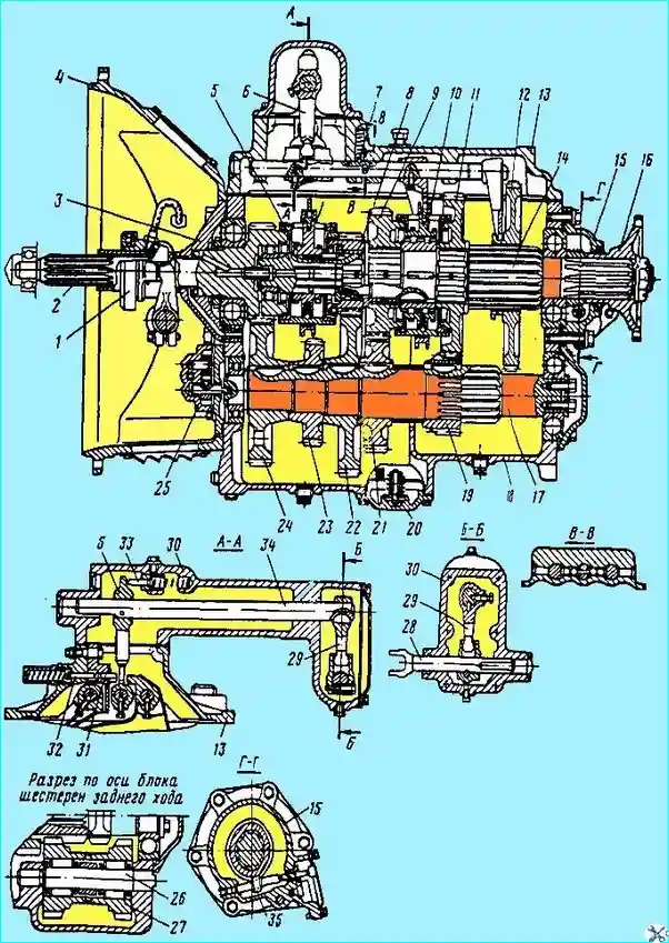
Fig. 1. Gearbox: 1 - clutch release sleeve; 2 - drive shaft; 3 - drive shaft bearing cover; 4 - clutch housing; 5 - fourth and fifth gear synchronizer; 6 - gear shift lever; 7 - lock with spring; 8 - fifth gear pinion of driven shaft; 9 - third gear pinion of driven shaft; 10 - second and third gear synchronizer; 11 - second gear pinion of driven shaft; 12 - first gear and reverse gear pinion of driven shaft; 13 - gearbox upper cover with rod and forks; 14 - driven shaft; 15 - driven shaft bearing cover; 16 - flange; 17- intermediate shaft with first gear pinion; 18 - gear chart; 19 - intermediate shaft second gear pinion; 20 - oil pump intake with magnet; 21 - intermediate shaft third gear pinion; 22 - intermediate shaft fifth gear pinion; 23 - power take-off pinion; 24 - intermediate shaft drive pinion; 25 - oil pump; 26 - reverse gear block axle; 27 - reverse gear block; 28 - rod; 29 - intermediate lever; 30 - crankcase; 31 - first gear and reverse gear shift linkage; 32 - reverse code engagement fuse with spring; 33 - pin; 34 - shaft; 35 - speedometer pinion worm
- - Unscrew the bolts securing the upper cover 13 to the gearbox housing 18, remove the upper cover from the housing together with the rod and forks and the cover gasket.
- - Unscrew the bolts and remove the power take-off hatch covers and their gaskets.
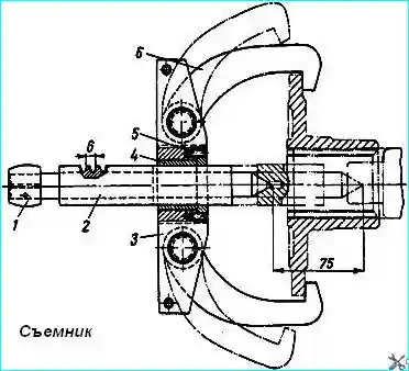
- - Unscrew the flange fastening nut 16, having first removed the cotter pin, remove the disc washer and use a puller (Fig. 2) to remove the flange 16 (see Fig. 1) securing the cardan shaft to the gearbox driven shaft.
Unscrew the bolts of the cover 15 of the rear bearing of the driven shaft, remove the cover with the oil seal and the speedometer drive.
- - Remove the clutch spring 1 clutch engagement, unscrew the nut securing the hose for lubricating the bearing to the clutch housing 4, unscrew the hose assembly from the clutch release coupling and remove the coupling 1 assembled with the bearing from the cover 3 of the rear bearing of the drive shaft.
- - Unscrew the tightening bolt of the clutch release fork, remove the spring washer from it and, pushing the shaft of the clutch release fork with the splined end forward, remove the fork.
Then knock out the key from the shaft groove and remove the shaft from the hole in the clutch housing 4.
During general disassembly, perform the following operations
- - Unscrew the bolts securing the cover 3 of the rear bearing of the drive shaft 2, remove the cover 3 assembled with the oil seal and remove the drive shaft 2 assembled from the housing 18 of the gearbox, using puller.
- - Move driven shaft 14 assembled forward until the rear bearing comes out of the seat, remove the retaining ring from the annular groove with pliers and press the rear bearing and worm 35 of the speedometer drive gear off the driven shaft with a puller.
After this, remove shaft 14 assembled from gearbox housing 18 and remove the first and reverse gears from its splined surface.
- - Unscrew the bolts securing oil pump 25 to the gearbox housing, remove pump 25 assembled and gaskets.
- - Unscrew the bolts of the intermediate shaft rear bearing cover 17, remove the cover gasket. Remove the safety wire, two bolts securing the thrust washer of the rear bearing of the intermediate shaft 17 and remove the washer.
Remove the axle 26 of the reverse gear block and the gear block 27 with bearings. Remove the roller bearings and spacer sleeve from the reverse gear block 27.
Move the intermediate shaft 17 as an assembly until the intermediate shaft rear bearing comes out of the gearbox housing 18 socket, use pliers to remove the retaining ring from the bearing groove, press the bearing off the shaft and remove the intermediate shaft 17 as an assembly with the gears from the gearbox housing.
- - Remove the cotter pin wire, unscrew the clutch housing fastening bolts 4, remove the spring washers from the bolts and remove the clutch housing from the gearbox housing 18.
Then unscrew the oil level plug and oil plugs from the gearbox housing oil channel.
Final disassembly of the gearbox involves complete disassembly of the following units and mechanisms:
- - driven shaft and rear bearing cover;
- - intermediate and driving shafts;
- - gearbox remote control mechanism;
- - gearbox upper cover;
- - oil pump.
When disassembling the driven shaft and rear bearing cover, perform the following operations.
Install the driven shaft 14 (see Fig. 1) assembled with gears on a stand with the threaded end in a vertical position.
Remove the spring thrust ring from the annular groove, remove the front bearing, synchronizer 5 of the fourth and fifth gears from the shaft and remove the locking key with a thrust washer 8 fifth gear pinion.
Insert a steel drift between the internal engagement teeth of 8 fifth gear pinion and the thrust washer and, rotating the pinion, disengage the thrust washer from the splines of the driven shaft.
Remove 8 fifth gear pinion of the driven shaft and the thrust washer of the fifth gear pinion.
Remove 9 third gear pinion and 10 second and third gear synchronizer from the shaft.

Fig. Puller
Having rested against gear 11 of the second gear, press the sleeve of gear 8 of the fifth gear, the sleeve of gear 9 of the third gear and the spacer sleeve of gears of the second 11 and third 9 gears from the shaft on a press.
Remove gear 11 of the second gear, the thrust washer of the gear of the second gear from the driven shaft and knock out the segment keys from the grooves of the shaft.
Having removed the cotter wire, unscrew the bolts of fastening of the replaceable gears from the cover 15 of the rear bearing of the driven shaft, remove the cover and the cover gasket.
Unscrew the cap of the cover of the replaceable gears, remove the gasket, take out the shaft of the driven cylindrical gear of the speedometer drive and take out the gear of the speedometer drive from the cover.
Having installed the cover 15 on the support with the plane of connection with the gearbox housing, press out the oil seal assembly from it.
When disassembling the intermediate shaft, do the following:
- - remove the front bearing thrust ring from the intermediate shaft 17, press off the front bearing and remove the thrust ring of the intermediate shaft drive gear 24;
- - press off from the intermediate shaft one by one: gear 24, gear 23 of the power take-off drive, gear 22 of the fifth gear and gear 21 of the third gear.
In each case of pressing the gears, knock out the keys from the grooves of the intermediate shaft;
- - remove the spacer sleeve, press off gear 19 of the second gear and knock out the segment key.
When disassembling the drive shaft 2, unscrew the ring nut, remove the retaining ring from the bearing ring groove with pliers and press the rear bearing with a puller, and then press the oil seal out of the cover 3.
When disassembling the gearbox remote control mechanism, perform the following operations.
After securing the mechanism in a vice, unscrew the bolts securing the crankcase cover 30 of the mechanism, remove the cover and gasket from the crankcase.
Bend back the lock washer, unscrew the bolt securing the rod head 28, remove the rod and the rod head.

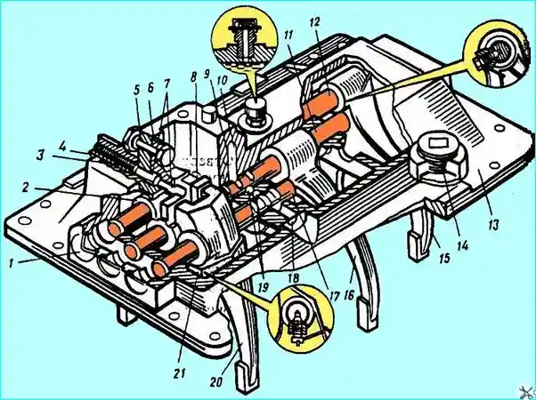
Fig. Gearbox cover: 1, 18 - plug; 2 - head of the reverse gear fork rod; 3 - safety spring; 4 - spring cup; 3 - link shaft; 6 - link: 7 - reverse gear safety devices; 8 - head of the 1st and 2nd gear fork rod; 9 - locking ball; 10 - locking spring, 11 - 1st and 2nd gear fork rod; 12 - reverse gear fork rod; 13 - top cover; 14 - plug: 15 - reverse gear fork; 16 - 1st and 2nd gear fork; 17 - 3rd and 4th gear fork rod; 19 - rod lock ball; 20 - 3rd and 4th gear fork; 21 - lock bolt
Unscrew the set screw, having first removed the cotter wire, pull out the shaft 34 from the housing 30 of the mechanism, simultaneously removing the gear shift lever 6 from it, and knock out the segment key from the groove on the shaft.
After removing the cotter wire, unscrew the set screw of the intermediate gear shift lever 29, remove the intermediate lever and knock out the segment key from the groove of the shaft.
Unscrew the oil filler and drain plugs from the housing.
Unscrew the lock screw with the washer from the housing 30 and remove the bushing, the limiter pin 33 and the limiter pin spring from the housing.
Remove the rod sealing ring from the housing 30 2
If necessary to perform repair work, remove the technological plugs from the crankcase
When disassembling
- - unscrew the breather 13 and oil filler plug 14 from the cover;
- - unscrew the cup 4 of the spring safety catch together with the spring;
- - unscrew the nut of the axle 5 of the leash 3, remove the spring washer, knock out the axle 5, remove the leash from the axle and remove the gear lock pin from the crankcase;
- - install the gearbox cover with the gear shift forks facing up;
- - remove the plugs 1 of the rods, move the rod 17 of the fork 20 for shifting the third and fourth gears forward to the extreme position;
- - unscrew the locking bolt 21, knock out the rod 17 from the fork 20 and remove it from the cover socket 13;
- - unscrew the locking bolts from the fork 15 for engaging reverse gear and the head 2 of the rod and knock out the rod 12 from the fork 15, the head 2 and the sockets of the cover 13;
- - unscrew the locking bolts of the fork 16 for switching the first and second gears and the head 8 of the rod, having first removed the cotter wire, and knock out the rod 8 from the fork 16 and the head
- - remove the pin and balls 7 of the rod lock from the cover 13, having first knocked out the plug 18, balls 9 and springs 10 of the locking rods of the gear shift forks.


